114-94438 REV C1
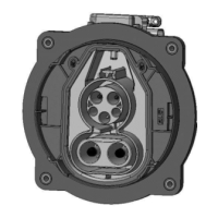
Step 14
Assemble Protection Cap [Pos. 14] at Inlet Housing [Pos. 1] as shown in the Figure 48
Typical press-on-force = 10N; max. press-on-force = 100N.
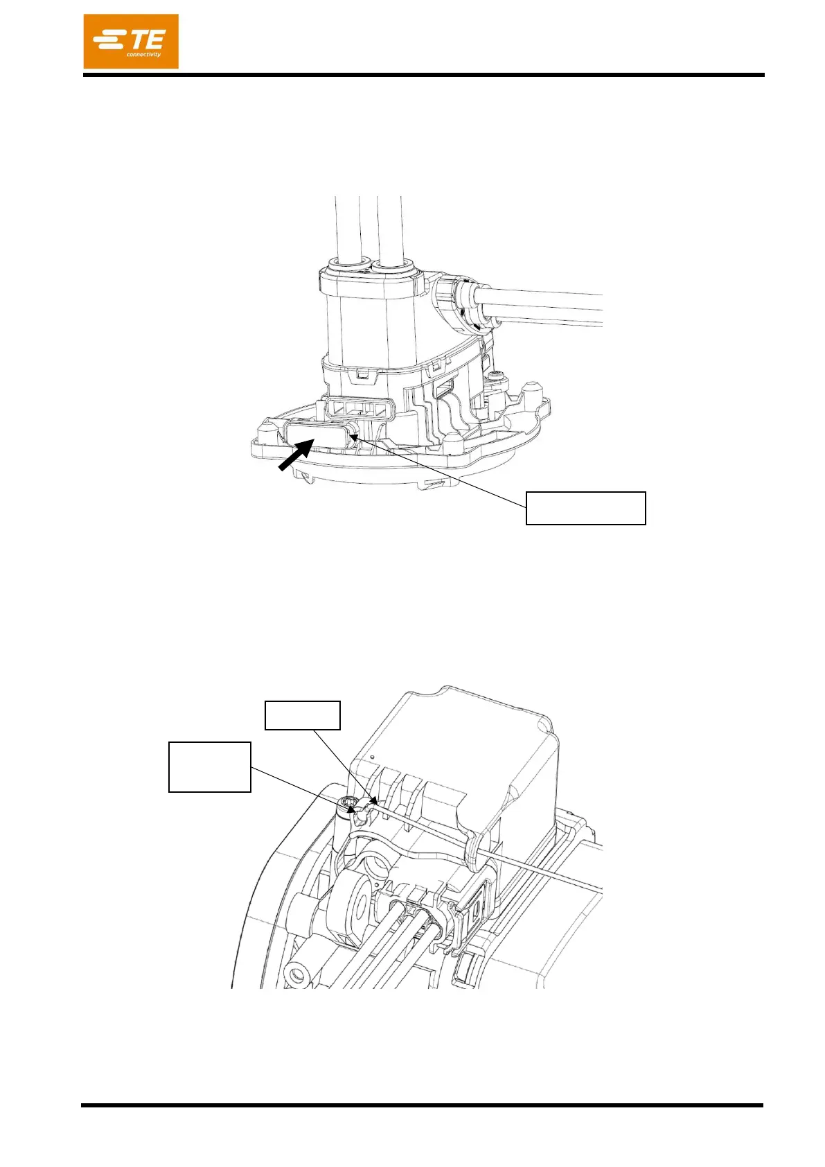
Step 15
Thread the service unlock ball wire through the hole in the actuator housing.
Snap the ball into the seating of the red unlocking strap as shown in the figure 49. Typical press-in-
force = 10N; max. press-in-force = 50N.
Ensure that the ball is fixed well by pulling and pushing at the wire with a low force.