EasyManua.ls Logo

Teac A-6010GSL - Overall Frequency Response and Recording Equalization Adjustment

Teac A-6010GSL
73 pages
Print Icon
To Next Page IconTo Next Page
To Previous Page IconTo Previous Page
Loading...
OVERALL
FREQUENCY
RESPONSE
AND THE
RECORDING
EQUALIZATION
ADJUSTMENT
IMPORTANT:
1.
With
the
MONITOR
switch
at
TAPE,
and
the
OUTPUT
and
LINE
controls
at
their
specified
level
position.
2.
Place
BIAS,
EQ/LEVEL
switch
in
HIGH
position,
thread
Scotch
203
record
test
tape
on
the
unit.
3.
Record
test
signal
approximately
30
seconds
each
of
a
variety
of
frequencies:
50,
100,
250,
400Hz;
1,
2.5,
5,
7.5,
10,
15,
20
kHz
at
7-1/2ips.
:
4.
Repeat
step
3
at
3~3/4ips
with
frequencies
from
40
Hz
to
10
kHz.
5.
Compare
the
outputs
with
the
frequency
response
chart
in
figure.
The
level
variation
should
not
exceed
40.5
dB
at
the
400
Hz
ref-
erence
point,
+1.5
dB
at
15
kHz.
At
3-3/4ips,
you
may
see
up
to
42
dB
at
10
kHz.
6.
If
adjustment
is
required,
adjust
L-102/202
at
7-1/2ips.
If
the
coil
adjustments
do
not
bring
the
response
within
limits,
then
adjust
C-140/240
at
7-1/2ips
and
C-141/241
at
3-3/4ips.
Make
these
adjustments
so
that
you
obtain
the
most
level
response
across
the
spectrum
in
reference
to
400
Hz.
7.
Repeat
steps
3,
4
and
5
with
Scotch
150
tape
and
set
the
BIAS
switch
to
NORMAL
position.
Response
should
be
flat
as
shown
before
the
dotted
portion
of
the
chart.
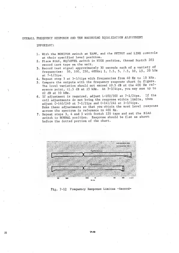
Fig.
7-12
Frequency
Response
Limites
-Record-