4-16
U 1 TECE urinal flush valve
Technical data 230 V/12 V mains transformer
Input voltage V AC (± %)
Frequency – Hz
Output Rated voltage V DC (± %)
Output voltage tolerance ± %
Residual ripple < mVpp
Output Rated current . A
Nominal power W
Minimum load
Energy eciency %
Electronic overload protection
Electronic short circuit protection
Type of protection IP
Protection class II
CE low voltage power
supply
Operating temperature – °C to + °C
Safety standard EN /EN
EMV standard EN /B
Technology Switching
Switching frequency KHz
Dielectric resistance , V/ min
MTBF (MIL HDBK) , h
Urinal flush valve assembly instructions
Note: This section provides instructions for the essential
points of installation. The notes are thus explained sections
from the overall assembly procedure. The entire installa-
tion procedure is shown in the assembly instructions for
the corresponding items.
The installation procedures for the mechanical and the
electronic flush valves are practically identical up to the
installation of the cartridge:
Flush out the pipe suciently.
Observe the following:
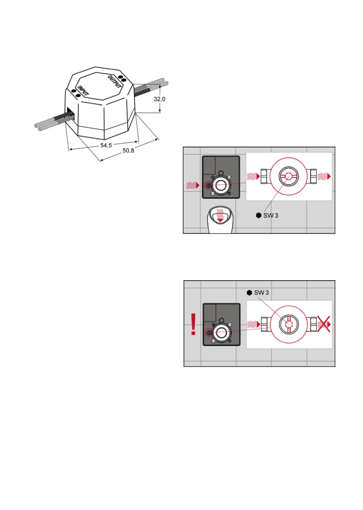
When performing the pressure test, the shut-o valve of
the flushing valve must be set to free-flow.
Before mounting the cartridge, ensure that the shut-o
valve is closed so that no water can leak out during assem-
bly. Close the shut-o using an Allen key. In the free-flow
setting, the goove of the shut-o is parallel to the housing,
and in the closed setting, it is at right angles to the hous-
ing.