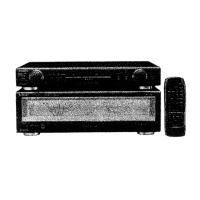
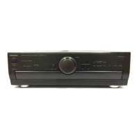
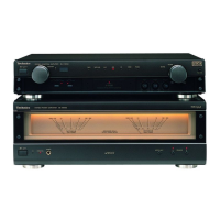
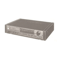
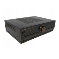
SE-A900SM2
|
m@
Contents
Page
|
Page
Before
Repalt
.......csccsccccsstesssecssesesssssssvesersnessnesesestssensesersseesrseeveesens
canes
2
Schematic
Diagram
......cccscescesssasssseeseecensscestenneeneseretennreraracaes
13~17
Protection
Circuitry
...-.....-..-cecsseneccteressceeecnncsaeersaeesansiaseenseseseanenenraeeenes
2
Printed
Circuit
Board
Diagram
........-c:csseseererensresersneteeneanes
SitAaces
18-21
ACCOSBONICS
........ccoscserscsssecrsococersrennsecsrasecsssnenscsseosesaseceseesavessecsacsestoorenes
2
Type
illustration
of
IC's,
Transistors
and
Di0d@
«.......sssessrssereerenre
21
Caution
for
AC
Mains
Lead
...........cssessecscecereceresstesssnenerssesasersreseereeses
3
—-—
Wiring
Connection
Dia
grain
......cccccsssrsersstersescsserseserererssensensssens
22
COMMECTIONS
...........ceceseeeesessseuerensessenes
sebsdsene
A
vidteoussswiwondetohiaostiaateeats
4,5
Block
Diagram
.........ccccccssssstecsscscsnrssoseccessrreazsreseranenensetensrarseseessnssetane
23
Names
Of
Parts
..........:.::cccscessercccessnevessansenacensneseceeessaaan
ans
rauaseerrwssaneas
eaeas
6
Repiacement
Parts
List
(Electrical)
.0...........
cece
eset
erreeresererereeaes
24,
25
OPOrations
.......cccecssercsssstensscenssencssssnesessereassssacsserecessscsnenneasesecatsanenees
es
7
Replacement
Parts
List
(Resistors
and
Capacitors)...............0.
26,
27
Operation
Check
and
:
Cabinet
Parts
LOCATON
.......ccecscesccscsscecssseercccsseasenasstartenresererenees
28,
29
Main
Component
Replacement
Procedures
.........-...:--cseeceeees
8-11
Replacement
Parts
List
(Cabinet,
Accessories
and
Packing)...........
30
Measurements
and
Adjustment
...........cc:scesccesrecsneercsteitesreneenianes
12
PACKAGING
.......scccecesescccseserseceosssserersscscessesarsrsstocsrerebeeserranseaserenanasnsnsese
31
m@
Before
Repair
|
(1)
Turn
off
the
power
supply.
Using
a’
10
©,
10
W
resistor,
connect
both
ends
of
power
supply
capacitors
(C701,
C702)
in
order
to
discharge
the
voltage.
|
|
-
(2)
Before
turning
the
power
supply
on,
after
completion
of
repair,
slowly
apply
the
primary
voltage
by
using
a
power
supply
voltage
controlier
to
make
sure
that
the
consumed
current
at
50
Hz
in
NO
SIGNAL
mode
should
be
shown
below
with
respect
to
supply
voltage
230
V/240
V.
Power
supply
voltage
AC
230
V,
50
Hz
AC
240
V,
50
Hz
Consumed
current
160
mA
~
320
MA
160
~
320
mA
@
Protection
Circuitry
The
protection
circuitry
may
have
operated
if
either
of
the
following
conditions
is
noticed:
*
No
sound
is
heard
when
the
power
is
switched
ON.
e
Sound
stops
during
a
performance.
The
function
of
this
circuitry
is
to
prevent
circuitry
damage
if,
for
example,
the
positive
and
negative
speaker
connection
wires
are
“shorted’,
or
if
speaker
systems
with
an
impedance
less
than
the
indicated
rated
impedance
of
this
unit
are
used.
If
this
occurs,
follow
the
procedure
outlined
below:
1.
Switch
OFF
the
power.
2.
Determine
the
cause
of
the
cause
of
the
problem
and
correct
it.
3.
Switch
ON
the
power
once
again.
Note:
When
the
protection
circuitry
functions,
the
unit
will
not
operate
unless
the
power
is
first
switched
OFF
and
then
ON
again.
@
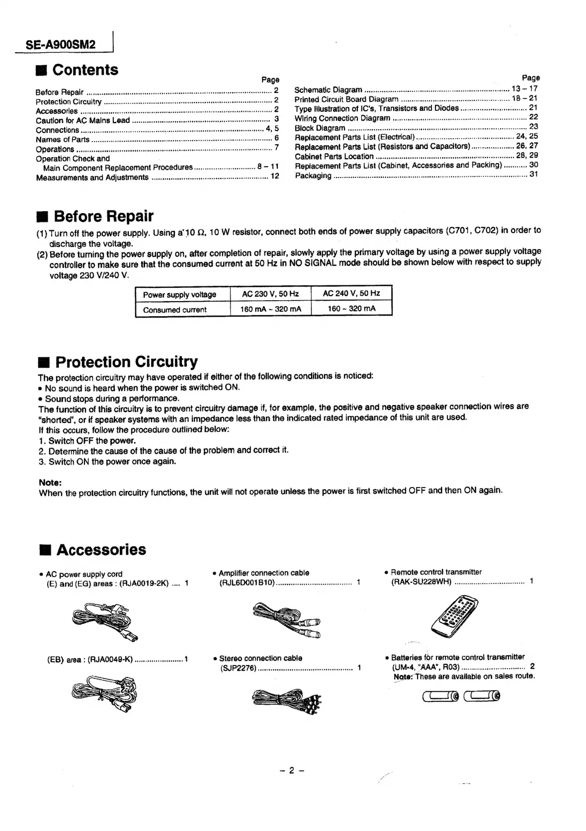
Accessories
¢
AC
power
supply
cord
«
Amplifier
connection
cable
e
Remote
control
transmitter
(E)
and
(EG)
areas
:
(RJA0019-2K)
....
1
(RIEB
DOOD
B10)
on
ccsccsiicesenbeccescereneeisns:
1
(RAK-SU228WH)
........
ee
cerns
reetetes
1
e
Stereo
connection
cable
e
Batteries
for
remote
control
transmitter
(SIPQ276)
vicestisdeatadcetess
cece
istecscesueneaistes
1
(UM-4,
“KAA’,
FROG)
:esiisscaverceansweceereceres
2
:
Note:
These
are
availabie
on
sales
route.
(C16
CI@