PCB TEST MODE Procedure
MAIN
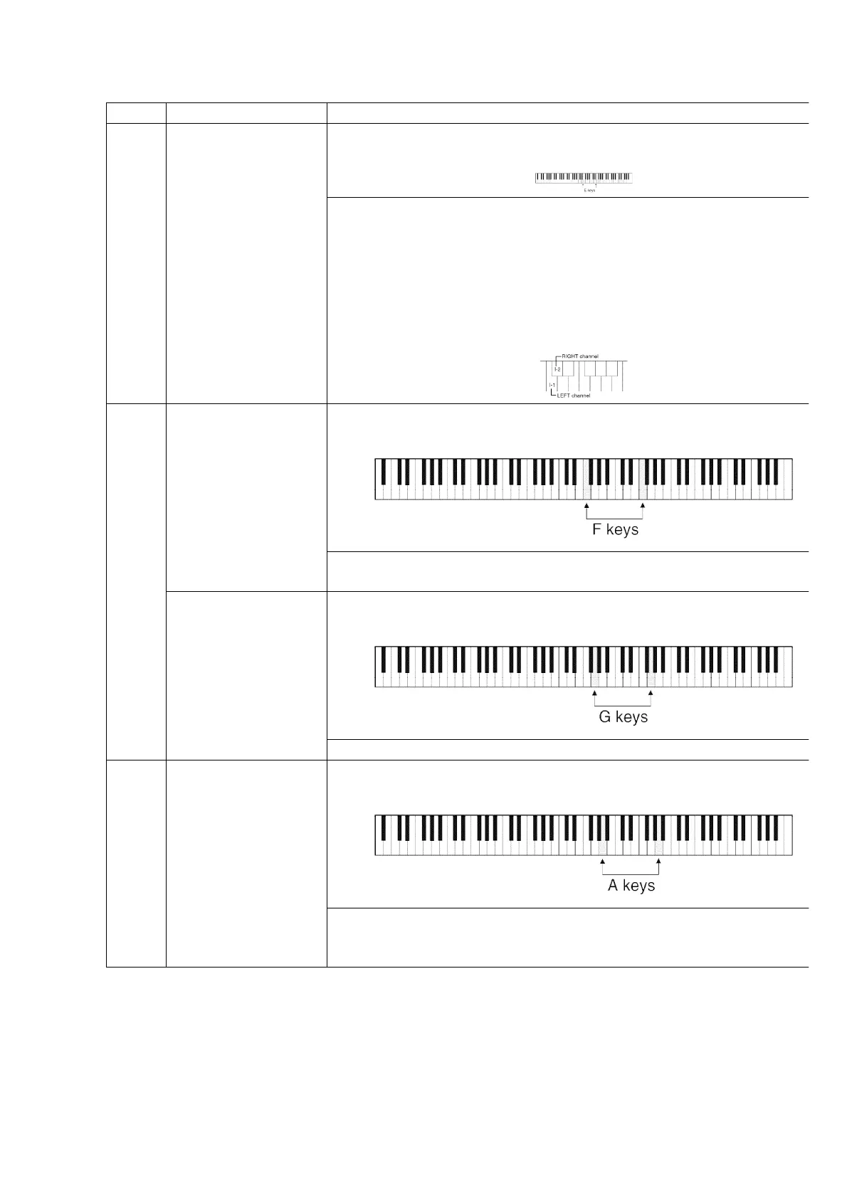
Wave ROM check
MAIN: IC12, IC18
1. Press and hold the two E keys shown below, and then turn on the power switch.
2. Select the POP GROUND sound.
3. Reduce the MAIN VOLUME level low enough.
When set to the self-diagnostic mode, the Wave ROM outputs a sine w
The Wave ROMs correspond to the keyboard keys as shown in the
diagram to the right. When a key is pressed, the corresponding sine w
sound is produced. If no sound is produced, or if the sound is distorte
the Wave ROM corresponding to that key is defective. This method all
to diagnose also the output routes (L/R) from the Wave ROM.
-
The key number indicates the Wave ROM number.
(I-1: IC12, I-2: IC18)
CPL
CPR
Control Panel buttons
LED lighting check
Press and hold the two F keys shown below, and then turn on the pow
switch.
Press the buttons on the control and confirm that the corresponding L
light.
Control Panel LED
display check
Press and hold the two G keys shown below, and then turn on the pow
switch.
The numbers are displayed automatically and repeatedly on the displa
MKB
Keyboard ROM (IC1)
check
Press and hold the two A keys shown below, and then turn on the pow
switch.
If the keyboard ROM (IC1) is OK, only the TOUCH SENSITIVITY LIGHT
flashes. If it is defective, the LEDs (LIGHT and NORMAL, or LIGHT,
NORMAL and HEAVY) flash.
9. PRECAUTIONS BEFORE SERVICING
9.1. Precautions for measuring of the output waveforms
1. The waveform was measured with a “National Digital Storage
14
www.freeservicemanuals.info