AInstallation
D
Ref. DCD01/3078 - TD412_en_C
26/62
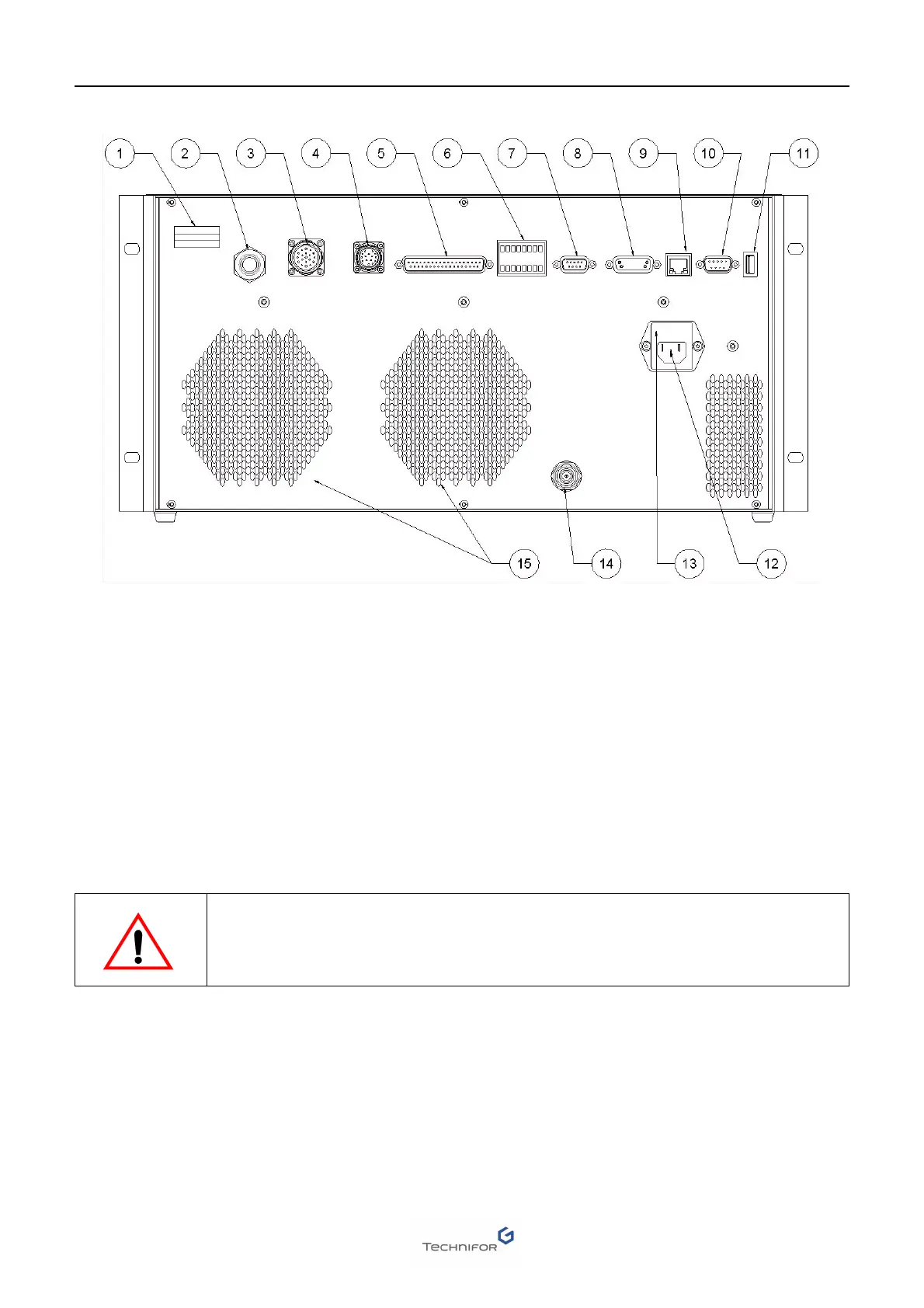
Control Unit - View of connectors
1 : Time meter (laser diode)
2 : Optical fiber (the optical fiber is not disconnectable on the marking head side, only on the CCU side)
3 : 19 point connector - Head/CCU connecting cable (cable supplied): marking-head signals
4 : 17 point connector - Head/CCU connecting cable (cable supplied): X-Y signals
5 : 37 point connector (DB37F): external signals
6 : I/O connector
7 : DB9F connector: I2C
8 : Connection for circular marking device (DB15F)
9 : Ethernet connection (RJ45)
10 : RS232 link (DB9M) (cable supplied)
11 : USB connector
12 : 110 - 230 V AC / 10 A power connection (cable supplied)
13 : Fuse
14 : RF cord for module/CCU connection
15 : Air outlet
Never switch on the CCU without first connecting the optical fiber and the RF
connection cord.