BIKE XT: Service & Maintenance manual - rev. 2.0
Page 6.6
Follow the procedure step by step to correctly diagnose the problem. Take particular care with the
checks highlighted by circled numbers, which are described in detail below:
(1) Perform the troubleshooting procedure described in paragraph 6.3. “The RPM value is
incorrect”.
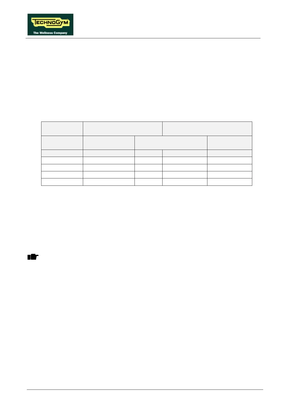
(2) Place the tester probes between the orange (positive) and black (negative) cables on the
alternator. Select the “Manual Training” function on the display and start using the machine.
Vary the level of difficulty, while maintaining the speed specified in Table 6.2-1: the excitation
voltage should vary as shown in the same table.
RPM = 70 EXCITATION VOLTAGE
(VDC)
WAVEFORM FREQUENCY
(Hz)
LEVEL OF
DIFFICULTY
ALTERNATOR ALTERNATOR
INTERFACE BOARD
CPU BOARD
4-5/CN2 6-3/CN1 6-3/CN1
1 1.5 1.5 155 155
3 2.3 2.3 250 250
6 3.2 3.2 360 360
9 4.6 4.6 510 510
Table 6.2-1
Note that the voltages and frequencies specified above are nominal values.
(3) As for point (2) but with the tester between pins 4 (positive) and 5 (negative) of connector
CN2 on the alternator interface board.
(4) Disconnect all the cables from the 2 power resistor terminals. Place the tester probes on the 2
terminals and measure the value of the resistance.
OBSERVE: Because all tester probes have a non zero internal resistance, which varies
depending on the model and may be in the same order as the quantity being measured,
the following procedure is recommended:
• Measure the internal resistance of the probes by short-circuiting them with each other;
• Measure the resistance of the power resistor. The true resistance value is obtained by
subtracting the short-circuit resistance of the probes from the measured value.
The correct value for the power resistor is approximately 0.5 Ω.
(5) As for point (2) but with an oscilloscope (if available) between pins 6 (probe) and 3 (ground)
of connector CN1 on the alternator interface board.
(6) As for point (5) but with the oscilloscope between pins 6 (probe) and 3 (ground) of connector
CN1 of the display CPU board.
 Loading...