BIKE XT: Service & Maintenance manual - rev. 2.0
Page 7.9
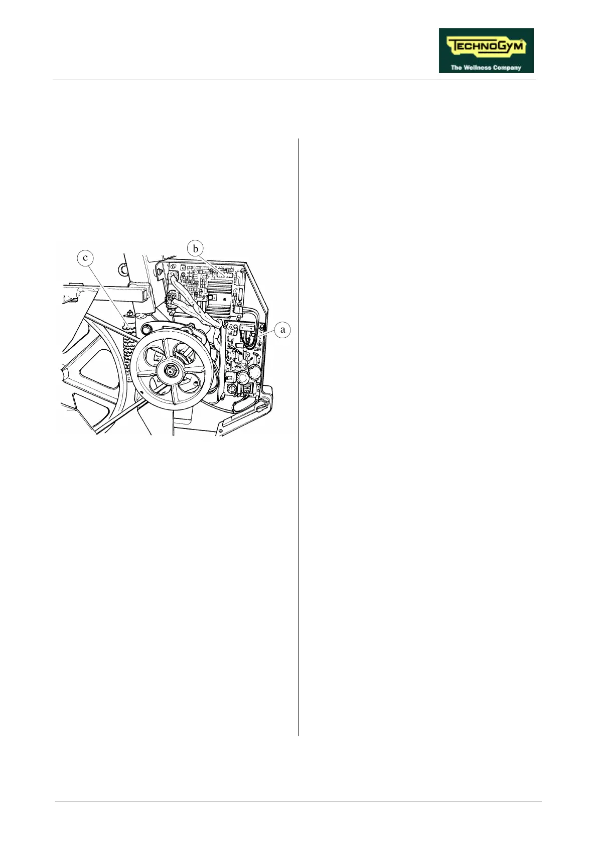
7.8. DISASSEMBLING THE ELECTRONIC CIRCUIT BOARDS
Figure 7.8-1
Carry out the procedure described in paragraph
7.7. “Disassembling the right and left side
casings”, removing only the right side casing.
1. Use a 7-mm wrench to unscrew the
hexagonal-head fixing screws of the grid
which protects the electronic circuit boards.
2. Remove the protection grid.
To disassemble POWER SUPPLY a:
1. Disconnect the 2 connectors CN1 and CN2.
2. Remove the fixing screws on the plate
support using a 7-mm socket wrench.
3. Manually unscrew the fixing studs on the
plate support.
4. Remove the circuit board.
To disassemble ALTERNATOR INTERFACE
BOARD b:
1. Disconnect the 3 connectors CN1, CN2 and
CN3.
2. Unscrew the fixing screws on the plate
support using a 7-mm socket wrench.
3. Manually unscrew the fixing studs on the
plate support.
4. Remove the circuit board.
To disassemble POWER RESISTOR c:
1. Unscrew the 2 locknuts on cable BX-5 using
a 7-mm wrench.
2. Unscrew the 2 locknuts on the resistor using
a 10-mm wrench.
3. Remove the resistor.
To reassemble the ELECTRONIC CIRCUIT
BOARDS, carry out the above steps in reverse
order.
 Loading...