BIKERACE: Service & Maintenance Manual - rev. 1.1
Page 3.6
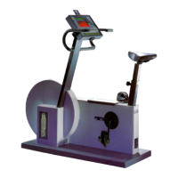
• RPM Signal
This is the speed signal output by the alternator. It enters the alternator interface board (pin 1-5
of connector CN2) and is a square wave which varies from –1 Vdc to a maximum value
dependent on the training speed, as illustrated in the figure below:
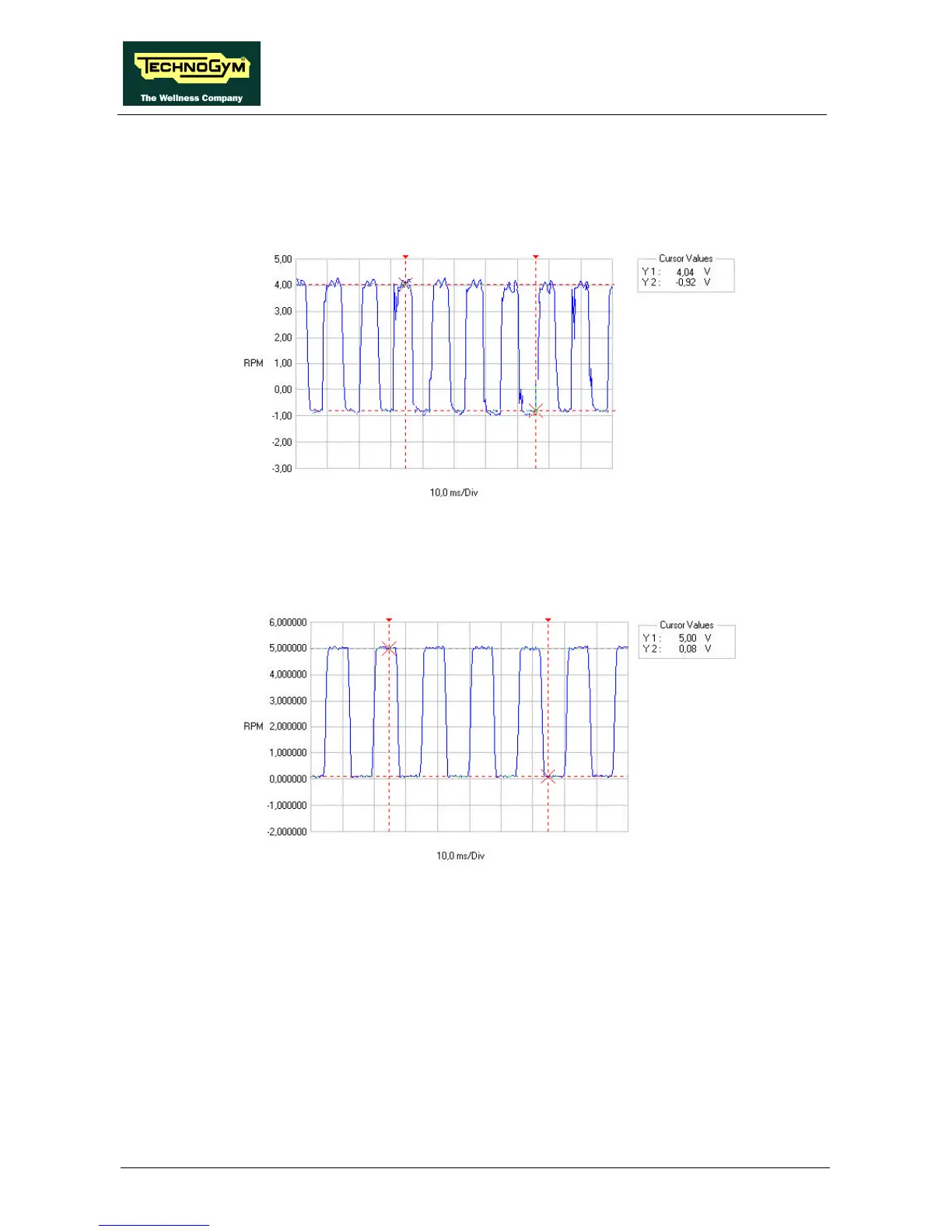
The signal is cleaned and level-converted before being sent from the alternator interface board
(pins 5-3 of connector CN1) to the CPU board (pins 5-3 of connector CN1) as a square wave
which varies between 0 and 5 Vdc, as illustrated in the figure below: