19
FLUXMASTER 50 INSTRUCTION MANUAL
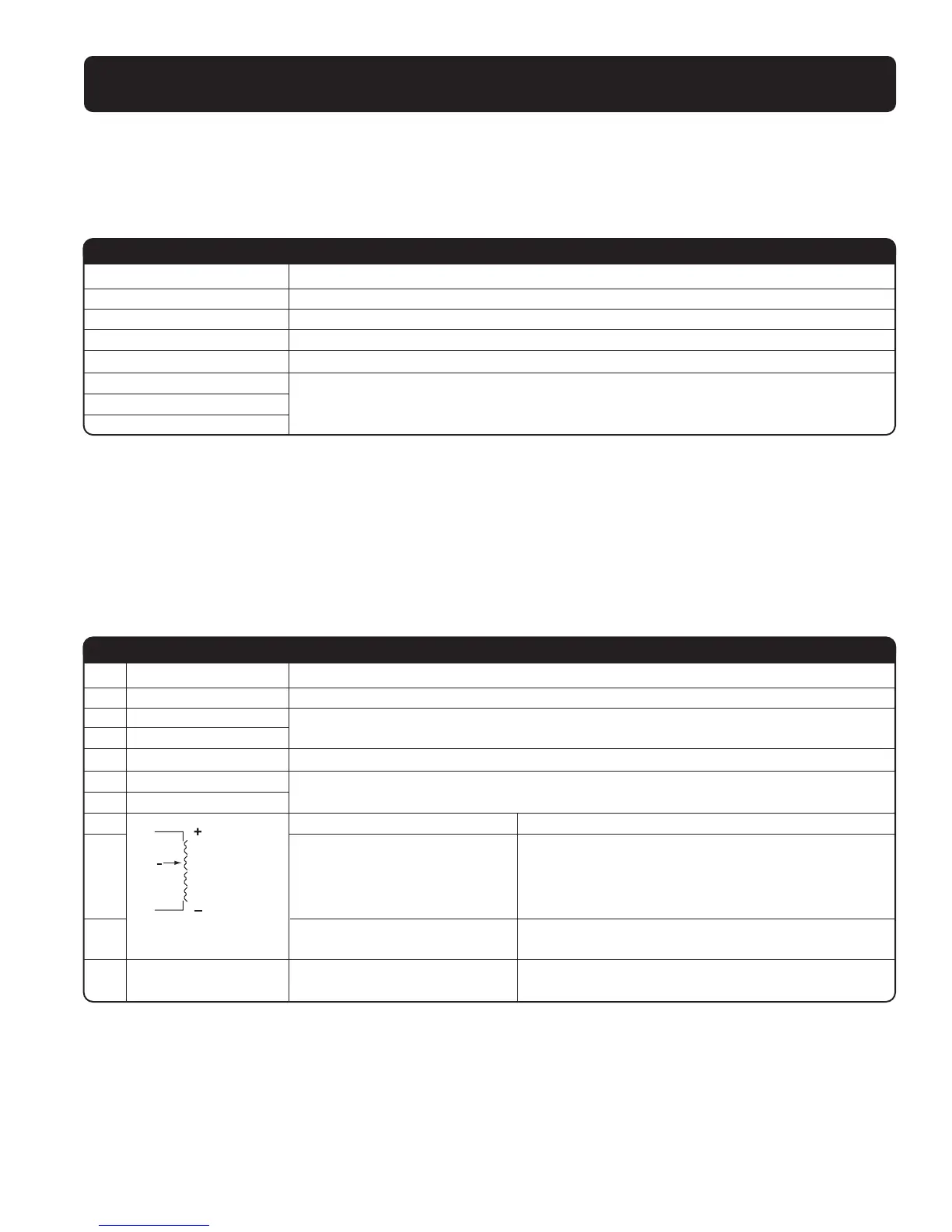
Inverter Terminal Descriptions, Primary Circuitry Terminal Block (TM1) Description
Terminal Symbol Function Description
L1/L (R) Primary power source input to Drive
L2 (S) Single phase: L1/L2 or L/N
L3/N (T) Three phase: L1/L2/L3
PExternal braking resistor terminal
R (230V, 2/3HP and 460V, 1-3HP models only)
T1 (U)
T2 (V) Inverter output to Motor
T3 (W)
Tightening torque for TM1 is 1lb-ft or 12lbs-in (all 115VAC models and 230V 1/4 - 1HP)
Tightening torque for TM1 is 1.3lbs-ft or 16lbs-in (230V 2, 3HP and 460V 1-3HP)
* Wire voltage rating must be a minimum of 300V(200V series)/600V(400V series)
Control Circuitry Terminal Block (TM2) Description
Terminal Symbol Function Description
1 TRIP Fault relay output terminal (Multi-Function output terminal) (see parameter F_21)
2 RELAY Connection point rated capacity 250VAC/1A (30VDC/1A)
3 FWD (FW)
Operation control terminals (see parameter F_03)
4REV (RE)
5+ 12V(12) Common point for terminals 3 / 4 / 6 / 7
6 SP1(SP)
Multi-Function input terminals (see parameter F_19)
7 RESET(RS)
8 +10V Power terminal for potentiometer (Pin 3)
Analog input wire
Analog frequency signal input terminal (Pin 2 of
9potentiometer or positive terminal of 0~10V /
4~20mA / 0~20mA)
Wiper
10
0V(FM -)
Analog common
Analog signal common point (Pin 1 of potentiometer)
or negative terminal of 0~10V / 4~20mA / 0~20mA)
11 FM+
Analog output positive Analog frequency signal output terminal
connection point Output terminal signal is 0 ~ 10VDC/Fn_6
Tightening torque for TM2 is 0.42lb-ft or 5.03lbs-in.
* Wire voltage rating must be a minimum of 300V.
* Control wiring should not run in the same conduit or raceway with any power or motor wiring.
* Single Input and Output Terminals (TM2) Ratings are ALL Class 2.
* Use copper conductors only. Size field wiring based on 167˚F (75˚C) wire only.


 To Next Page