43
FLUXMASTER 50 INSTRUCTION MANUAL
F_14 Stopping Method = 0 : Controlled deceleration stop
= 1 : Coast to stop
F_15 DC Braking Time = 0 ~ 25.5 sec
F_16 DC Braking Starting Frequency = 1 ~ 10Hz
F_17 DC Braking Level = 0 ~ 20%
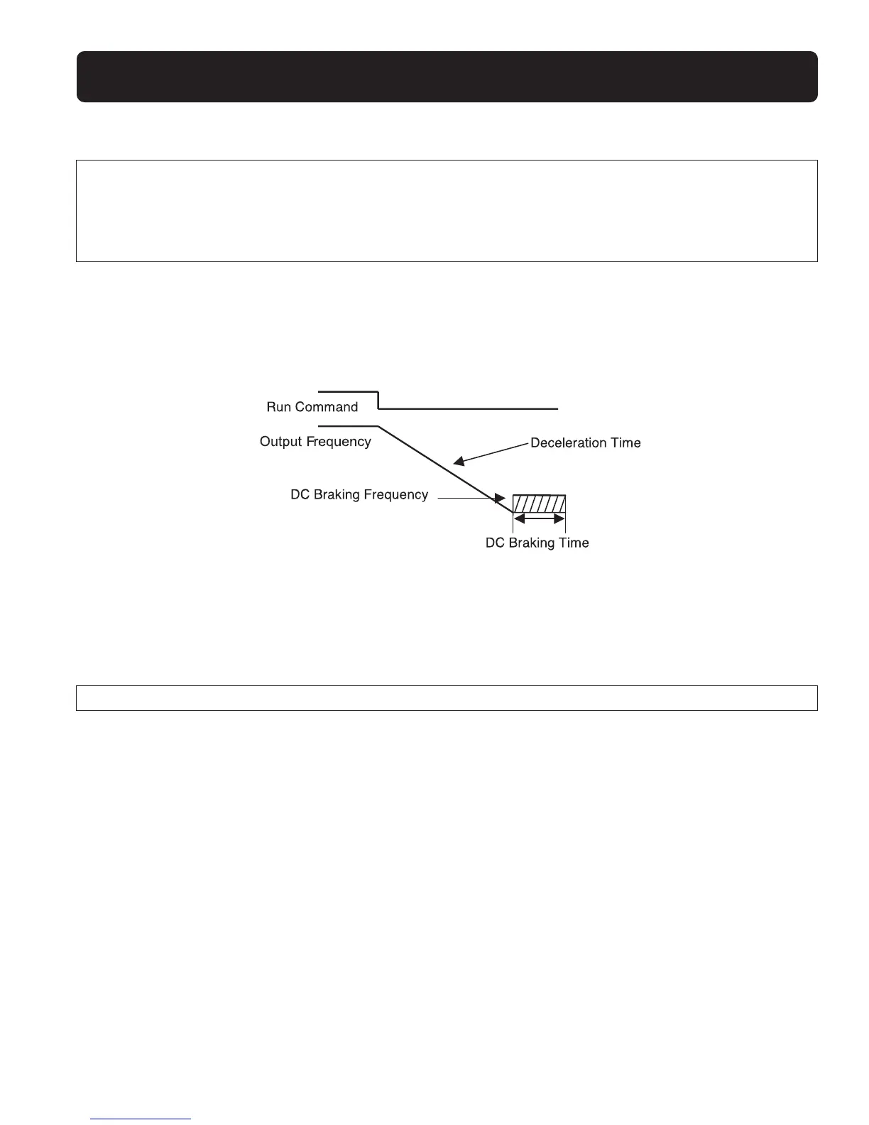
If F_14 = 0
When the AC drive receives the stop command,it decelerates to the preset frequency set by F_16.After this, the output voltage
level that is set in F_17 will determine the amount of DC voltage that is injected into the motor.The time duration to perform this
stopping function is set in F_15.
If F_14 = 1
The inverter stops output immediately after receiving the stop command.The motor will enter into a coast to stop state until it
comes to a complete stop.
F_18: Motor Rated Current = 50 ~ 200%
1.The electronic thermal overload protection for the motor is as follows:
(1) Motor rated current = AC drive rated current x F_18.(F_18 = Motor rated current / AC drive rated current)
(2) When the load is within 100% of the motor’s rated current,the operation continues.When the load reaches 150% of the
motor’s rated current,the operation is allowed to continue for 1 minute.(Refer to curve (1) in Figure 3)
(3) After protecting the motor with the electronic thermal switch activated, the AC drive is cut off immediately.The OL1 light
will flash.To resume operation, push the RESET button or activate an external reset contact wired to Terminal 2.
(4) When the motor is operating at low speeds, the heat dissipation efficiency is lower.The electronic thermal activation level is
also reduced. (to change from curve (1) to curve (2) in Figure 3.Choose the appropriate F_05 setting according to the applied
motor to reach the desired performance.
 Loading...