2-17
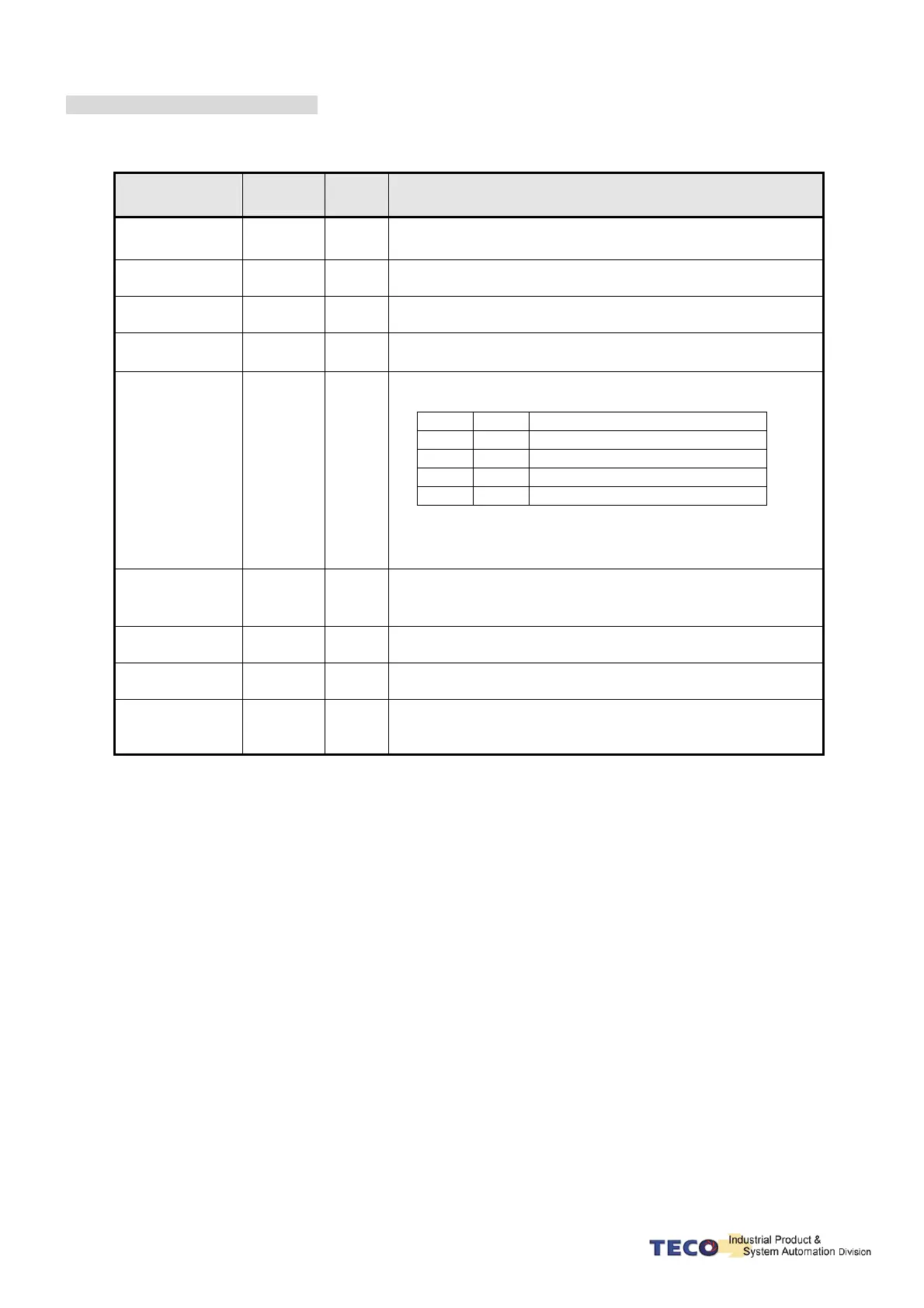
Digital Input Function Explanation
(Except CCWL and CWL are the high electric potential, other terminal layout are the low electric potential,
please refer to 5-6-1 to check related parameters setting)
Signal Name
Function
Symbol
Mode I/O Function
Control Mode
Switch
MDC
Pe/S/T
When MDC and IG24 close loop, current control mode will
transform into default control mode, please refer to Cn001.
Position
Command Limit
INH
Pe
When INH and IG24 close loop, position command input does
not operate (do not accept external pulse command).
Speed Command
Counter Wise
SPDINV
S
When SPDINV and IG24 close loop in speed mode, setting
rotating speed will become counter-wise rotating speed.
Gain Select
G-SEL
Pi/Pe/S
When G-SEL and IG24 close loop, first stage control gain
switch to the second control gain.
Electric Gear ratio
Numerator 1~2
GN1
GN2
Pi/Pe
Electric gear ratio: select explanation:
GN2 GN1 Electric Gear ratio Numerator
0 0 Pn302
0 1 Pn303
1 0 Pn304
1 1 Pn305
“1”: Close loop with IG24
“0”: Open loop withIG24
Internal Position
Command
Trigger
PTRG
Pi
When PTRG and IG24 close loop (positively-triggered), the
motor will select related position command to operate in
accordance with the terminal layout POS1~POS4.
Internal Position
Command Hold
PHOLD
Pi
When PHOLD and IG24 close loop(positively-triggered), the
motor will stay holding.
Home
SHOME
Pi/Pe
When SHOME and IG24 close loop(positively-triggered),
HOME function operates
External Origin
ORG
Pi
When ORG and IG24 close loop(positively-triggered), server
will use this as external reference point for home position
returning.