2-18
Digital Input Function Explanation
(Except CCWL and CWL are the high electric potential, other terminal layout are the low electric potential,
please refer to 5-6-1 to check related parameters setting)
Signal Name
Function
Symbol
Mode I/O Function
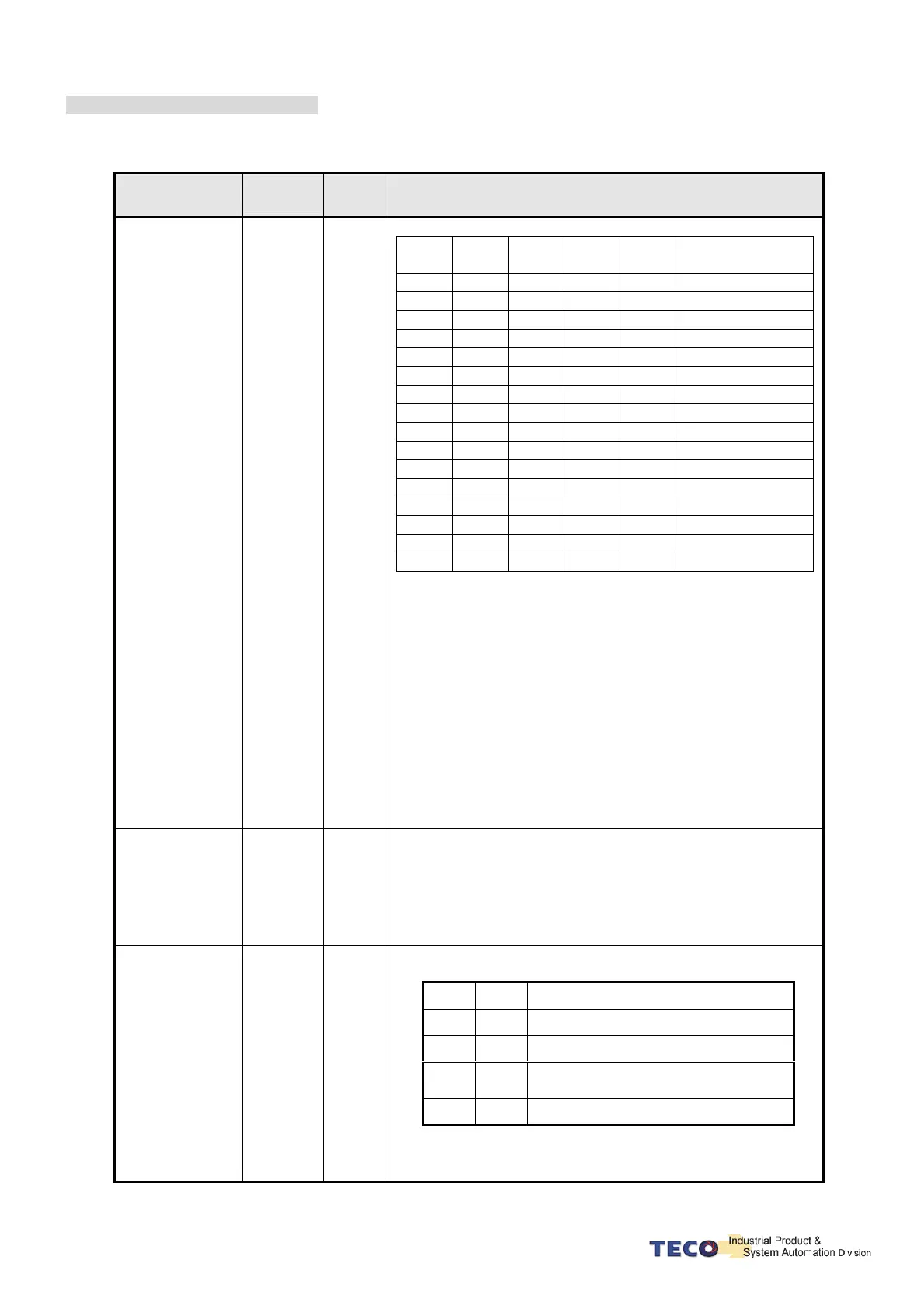
Internal Position
Command select
1~5
POS1
POS2
POS3
POS4
POS5
Pi
Internal position command select :
POS1 POS2 POS3 POS4 POS5
Internal Position
Command select
0 0 0 0 0
Pn317, Pn318
0 0 0 1 0
Pn320, Pn321
0 0 1 0 0
Pn323, Pn324
0 0 1 1 0
Pn326, Pn327
0 1 0 0 0
Pn329, Pn330
0 1 0 1 0
Pn332, Pn333
0 1 1 0 0
Pn335, Pn336
0 1 1 1 0
Pn338, Pn339
1 0 0 0 0
Pn341, Pn342
1 0 0 1 0
Pn344, Pn345
1 0 1 0 0
Pn347, Pn348
1 0 1 1 0
Pn350, Pn351
1 1 0 0 0
Pn353, Pn354
1 1 0 1 0
Pn356, Pn357
1 1 1 0 0
Pn359, Pn360
1 1 1 1 0
Pn362, Pn363
Internal position command select explanation:
“1”: close loop with IG24
“0”: open loop with IG24
Torque Command
Counter Clock
Wise
TRQINV
T
When TRQINV and IG24 close loop in torque mode, setting
torque command output wise becomes counter wise output.
External torque
command
direction select
RS1
RS2
T
External torque command direction select :
“1” means short with IG24.
“0” means open with IG24.
RS2 RS1 Statement
0 0 No torque command input
0 1 According to torque command
1 0
Opposite direction for currently torque
command
1 1 No torque command input