2-19
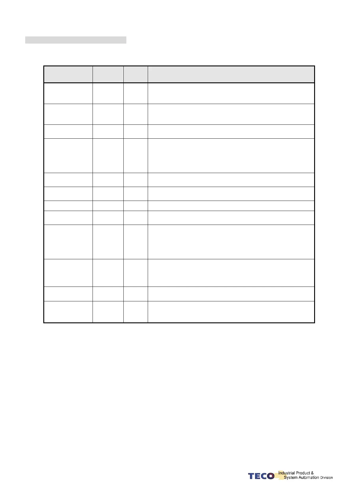
Digital Output Function Explanation
(The terminal layout here from this explanation are all the low electric potential, please refer to 5-6-1 to check
parameter settings)
Signal Name
Function
Symbol
Mode I/O Function
Servo Ready
RDY
ALL
Main power and control power input are normal. Under the
situation of no alarm, terminal layouts RDY and IG24 close
loop.
Alarm
ALM
ALL
If normally operates, the terminal layouts ALM and IG24 open
loop. When alarm occurs, protection-function operates, the
terminal and IG24 close loop.
Zero Speed
ZS
S
When the motor speed is less than the speed from Sn215, the
terminal layout ZS and IG24 close loop.
BK Signal
BI
ALL
When Cn008 is set “1” or “3” and the servo on, the terminal
layout BI and IG24 close loop; when servo off , terminal layout
and IG24 open loop. (When this terminal layout is generally
applied, it is the Brake relay, which is connected to control
motor).
In Speed
INS
S
When the motor speed has achieved the setting speed from
Cn007, INS and IG24 close loop.
In Position
INP
Pi/Pe
When the amount of position error counter is less than the
amount range which is set in Pn307, INP and IG24 close loop.
Home
HOME
Pi/Pe When HOME is accomplished, HOME and IG24 close.
Torque Reach
signal
INT
ALL
When the output torque reached the setting value of Tn108, INT
and IG24 close.
Limiting Torque/
Alarm No. 0
LM/A0
ALL
When motor output torque is limited by internal torque limit
amount (Cn010&Cn011) or external torque limit command
(PIC&NIC). LM/A0 and IG24 close loop.
When alarm occurs, this terminal layout is alarm code output
A0.
P in Action /
Alarm No.1
PC/A1
Pe/Pi/S
When speed loop is ratio(P)-control, PC/A1 and IG24 close
loop.
When alarm occurs, this terminal layout is alarm code output
A1.
Server in Limiting/
Alarm No.2
ST/A2
ALL
When CCW or CW operation-limit occurs, ST/A2 and IG24 close loop.
When alarm occurs, this terminal layout is alarm code output A2
Base Block/
Alarm No.3
BB/A3
ALL
When servo motor has not be operated, BB/A3 and IG24 close
loop.
When alarm occurs, this terminal layout is alarm code output A3