Betriebsanleitung/Operating manual
F2301/F23C1/F23S1
www.tecsis.de BD_BE_912 c 31
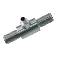
Type Model
Signal
Power supply
S# Product no.
UB+/S+ Pin assignment – power supply / signal +
0V/S- Pin assignment – power supply - / signal -
UR+, UR- Pin assignment – power supply Relay
S-Test SIL-Shift
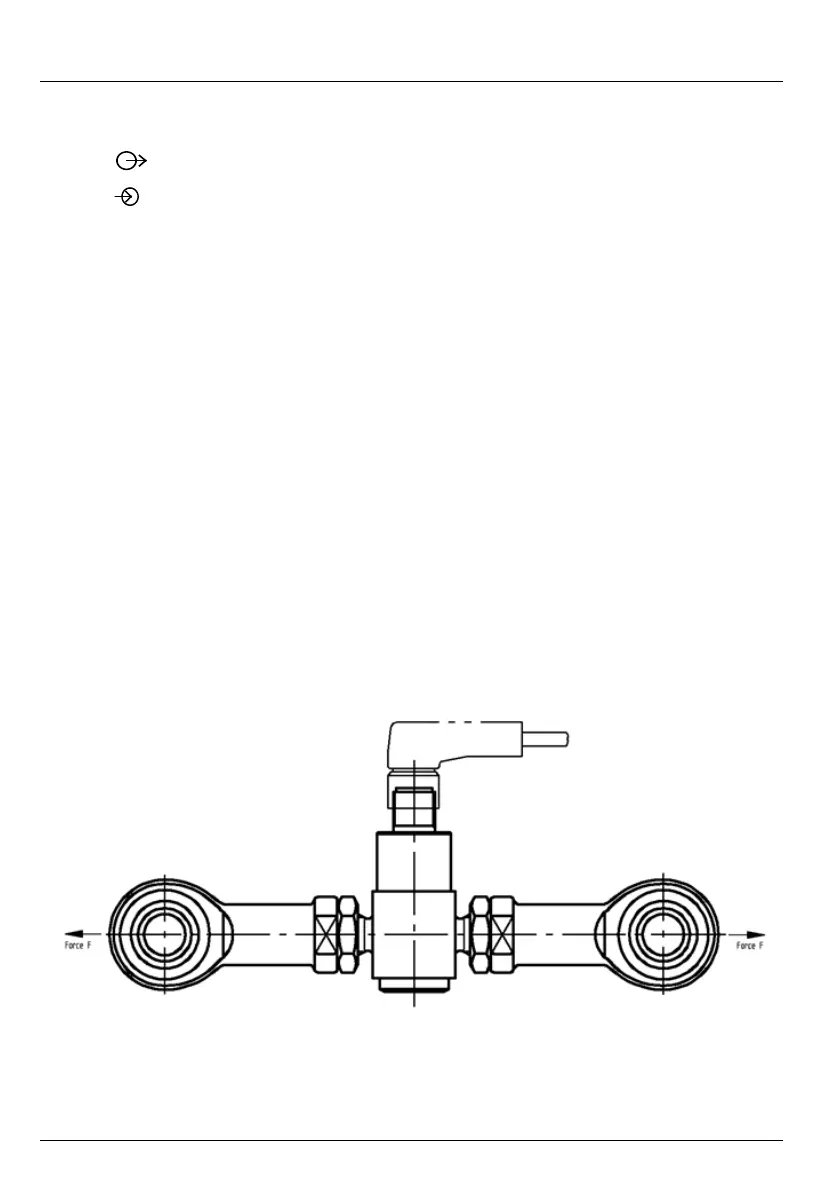
6.2 General installation guidelines
• The loads acting upon the load cell must be in the load direction.
• Tension and/or compression force in model series
F2301/F23C1/F23S1 is introduced via two axial threaded bolts.
• The supplied lock nuts must not come into contact with the defor-
mation body.
• In order to avoid interfering force, tecsis recommends the use of ar-
ticulated heads (see chapter 9).
Fig. 4 Installation situation of a tension/compression load cell