Betriebsanleitung/Operating manual
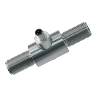
F2301/F23C1/F23S1
www.tecsis.de BD_BE_912 c 43
10.2 Fault remedying
Devices that are operated in potentially explosive areas must not be mod-
ified. The devices may only be repaired by specially trained and author-
ised experts. Defective devices should be returned to the manufacturer.
10.3 Electrical parameters
Ub+: 9 to 30V
Imax: 130mA
Pmax: 750mW
Ci: 13.2nF
For tension/compression load cells with cable connection include the
following values:
C
L
= 320nF/km
L
L
= 0.44mH/km
If a redundant design of the tension link is used, separate cable leads are
provided. Connecting via a single cable with the requirements of IEC
60079-14 are taken into account. Different intrinsically safe circuits in the
cable are separated by shielding. On the grounding of all shields should
be ensured. If two intrinsically safe circuits connected via a plug con-
nector to the load cell, the plug must be coated and the distances be-
tween the intrinsically safe circuits inside of the coating must be at least
1mm. The cable must be protected from damage. Damaged cables must
be replaced immediately.
The tension links with ignition protection type “ib” must only be sup-
plied using galvanically-isolated power supplies. Suitable supply
isolators are also optionally available eg. EZE08X030003.