Betriebsanleitung/Operating manual
F5301/F53C1/F53S1
www.tecsis.de BD_BE_907 c 31
6.2 General installation guidelines
• The loads operating upon the load pin must be introduced perpendic-
ular in the load direction.
• Torsion and shear forces need to be avoided. Components of angular
applied measured variables are also a part of transverse loads and
lateral forces.
• Torsional moments, transverse or centric loads and side forces cause
measurement errors and can damage the load pin permantly.
• The axle bracket grooves also serve as a reference for aligning and
fix the load pin against rotation.
• The DIN 15058 axle bracket must be attached in such a way that the
measuring axle is prevented from twisting in the bearing and does not
have any axial play. The axle bracket and the attaching must not be
loaded by example the axle load. The Axle bracket must be
secured with undetachable fixing.
• The measuring axle may only be subjected to load if the correct type
of bearing has been used. Loads occurring in other equipment may
change the zero signal and result in permanent damage.
• The introduction of force in the centre must not wander and must be
installed in such a way that axial shifts are prevented. However, force
by-passing may not occur.
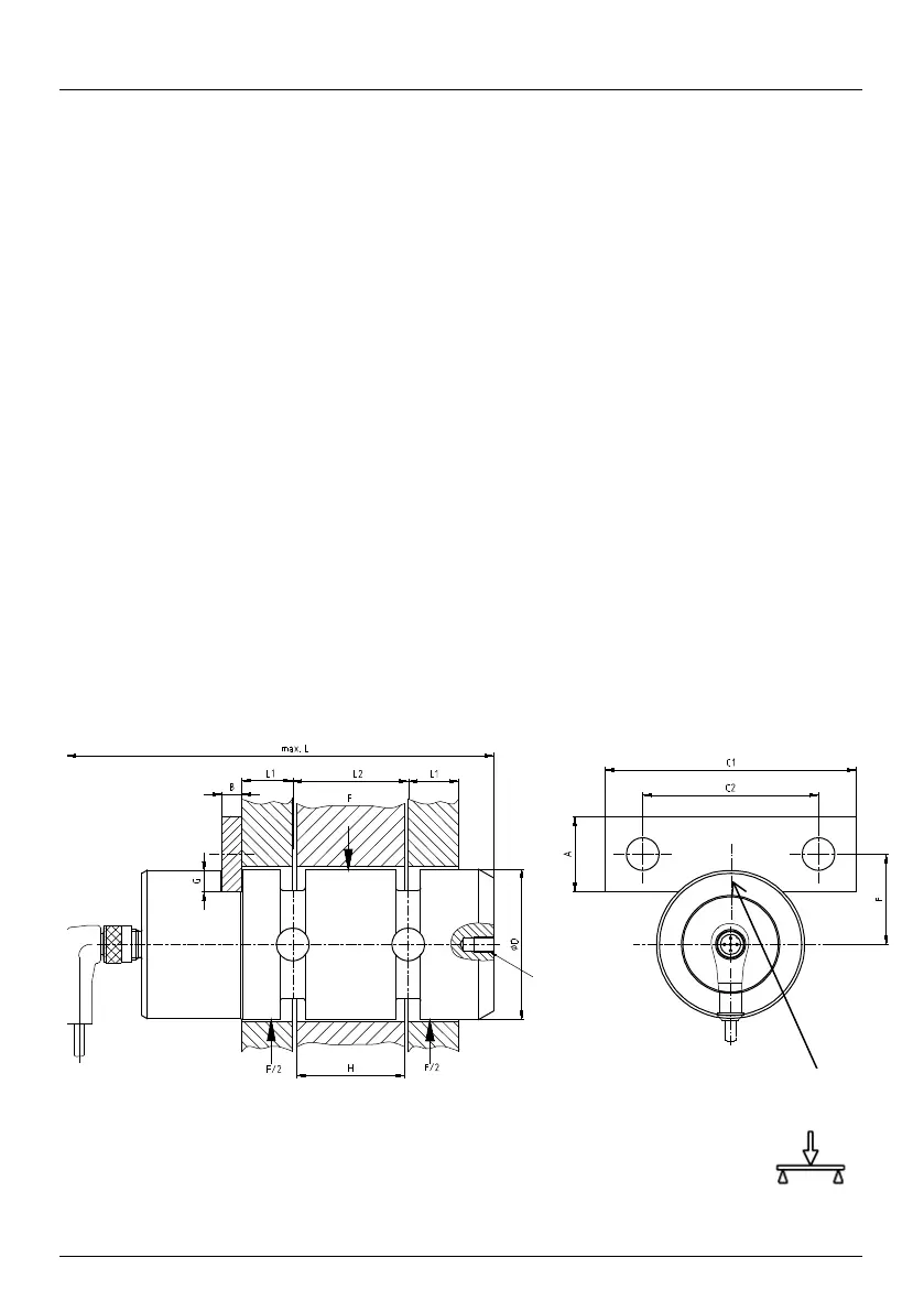
Fig. 4 Installation situation of a load pin
Axle bracket acc. to DIN 15058
nection
(M6 8/12
deep)
„force direction“