Betriebsanleitung/Operating manual
F7301/F73C1/F73S1
www.tecsis.de BD_BE 990 c 27
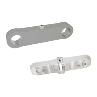
4 Design and method of operation
Measuring element 4.1
Innovative manufacturing methods using the strain gauge principle
have recently been developed. Etched wire strain gauges are not
used in this case. The entire Wheatstone bridge with the necessary
equalisation resistances and temperature compensation is realised
using a thin-film method on a metallic, pot-shaped body. The bridge
circuitry of the sensors is actively calibrated during the manufacturing
process using laser calibration. This thin-film sensor can now be in-
serted into an appropriately shaped measuring spring with the aid of a
laser welding method. The welded-in thin-film sensor and the optional
electronics are sealed against moisture and dust.
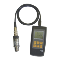
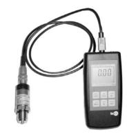
Measuring procedure and output signal 4.2
The force acting in the measuring direction causes the measuring
spring to become elastically deformed and therefore also the welded-
in thin-film cell. This deformation generates a resistance change in the
individual bridge resistors. If the measuring bridge is now supplied
with a feed voltage, a measuring signal that is proportional to the force
occurs at the bridge output. This signal can be output provided with
the aid of integrated amplifiers as standardised 4-20 mA, 0-10 V or as
a CANopen
®
output signal.
For the use in combination with the ELMS1 overload protection
only an opposing 4 ... 20 mA signal (redundant) is approved.
Therefore please note the instructions in the original operating
manual for ELMS1 overload protection.
5 Deployment location conditions
Ambient temperature 5.1
The temperature range of -20° C to +80° C that is specified in the data
sheet applies with regard to deployment. The specified error limits are
not guaranteed outside this temperature range. Temperature gradi-
ents in the tension links must be avoided if possible. One-sided or
local heating of the tension link can cause large measuring errors.
The temperature errors specified in the data sheet always relate
to the entire measuring device up to the plug or the end of the
cable (including the integrated amplifier).