Betriebsanleitung/Operating manual
F7301/F73C1/F73S1
www.tecsis.de BD_BE 990 c 31
7 Electrical connection
Electrical and magnetic fields often generate interfering voltage in the
measuring circuit. This interference essentially emanates from high
voltage current running parallel to the measuring lines, but can also be
caused by contactors or electric motors operating in the vicinity. Inter-
fering voltage can also be introduced galvanically. This particularly oc-
curs in cases where the measuring chain is earthed at various points
that do not have the same potential.
To avoid EMC problems, please note the following:
• Always use shielded, low-capacity measuring cables
(all tecsis cables meet these requirements).
• The shielded measuring cable should be grounded on both sides.
• Do not route the measuring cable parallel to high-voltage current and
control cables.
• Avoid leakage fields from transformers, motors and contactors.
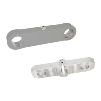
• The tension link, the amplifier and the processing or display unit
must not have multiple earths. Attach all equipment to the same pro-
tective conductor.
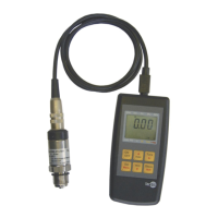
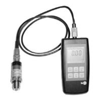
The plug or cable connection assignments can be found on the name
plate (Fig. 1 to 3, p. 28-29). Unless otherwise agreed, the following
assignments are used as standard.
Abbreviations for connection Abbreviations for colors
power supply + for Relay
(SIL-Shift)
power supply - for Relay
(SIL-Shift)