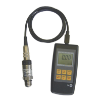
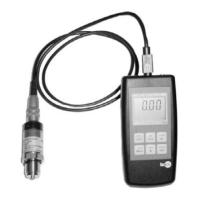
Betriebsanleitung/Operating manual
F7301/F73C1/F73S1
www.tecsis.de BD_BE 990 c 37
F73C1 Version
ATEX/IECEx Ex ib
1)
F73C1 Version
SIL-3 nach EN 62061:2005
Relative linearity error
2)
Temperature effect on zero signal
Temperature effect on characteristic value
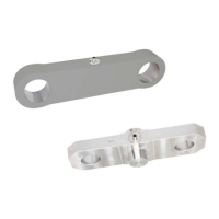
Mechanical characteristics
of measuring spring
corrosion resistant stainless steel or fine-grained steel with surface
protection, ultrasonic tested 3.1 material / (optionally 3.2)
Operating temperature range
B
T, G
°C
operating temperature range see
chapter 10.1 on a page 39
-30…80
Storage temperature range
Electrical characteristics
mA
Current output 4 … 20 mA
2-wire: signal current
2-wire: signal current,
Current output 4 … 20 mA
3-wire: < 8 mA,
VDC 10…30 for current output
10 … 30 VDC for current output
14 ... 30 VDC voltage output
urden
Ohm
≤ (UB–10 V)/0,024 A for current output
> 10 kΩ voltage output
≤ 2 (within 10% bis 90% F
nom
)
6)
Protection (acc. to EN 60529/IEC 529)
Vibration resistance
(acc. to DIN EN 60068-2-6)
20 g, 100 h, 50...150 Hz
Reverse voltage, overvoltage and short-circuit protection
acc. DIN EN 61326-1/DIN EN 61326-2-3
(optional EMC ruggedized version)
M 12x1, 4-pin;
MIL connector; Cable gland
Circular connector
M 12x1, 4-pin; Cable gland
Certificates, Strength tests,
3D-CAD data (STEP, IGES) on request
1)
The load pins with ignition protection type “ib” must only be supplied using galvanically-isolated power supplies.
Suitable supply isolators are also optionally available eg. EZE08X030003
2)
Relative linearity error is specified acc. to VDI/VDE/DKD 2638 chapter 3.3.6 b.
3)
Acc. to VDI/VDE/DKD 2638 Relative repeatability error in unchanged mounting position.
4)
This value can be reached when 100% F
nom
act. 90° rotated to the axis.
5)
Other SIL-shifts are available on request.
6)
Other response times are available on request.