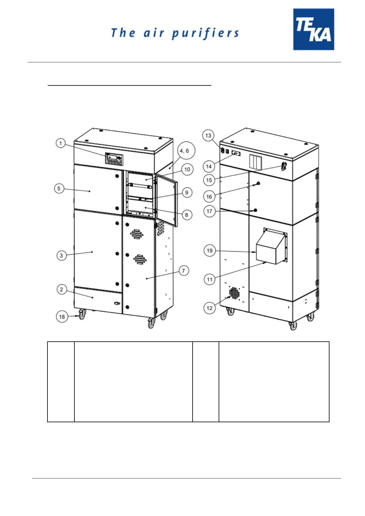
2. Description of the system elements
2.1. Illustration of the system elements
Installation example:
Z.Nr. 14261701
Pos.1
Pos.2
Pos.3
Pos.4
Pos.5
Pos.6
Pos.7
Pos.8
Pos.9
Pos.10
Operating panel of the control
Dust collecting housing
Filter housing
Particle filter housing
Cleaning housing
Activated carbon housing
Turbine housing
Particle filter
Intermediate frame
Activated carbon cassette
Pos.11
Pos.12
Pos.13
Pos.14
Pos.15
Pos.16
Pos.17
Pos.18
Pos.19
Suction nozzle
Exhaust grille
Connection for mains cable
Connection for external control unit
Industrial connector for the optional
gate valve
Connection for compressed air
Drain valve for compressed air
Swivel castor
Connection for Metering device
BA_LFE-101-201-301_ST1_20230808_EN