© 2020 521_D - 12/20
6 of 28
A Watts Water Technologies Company
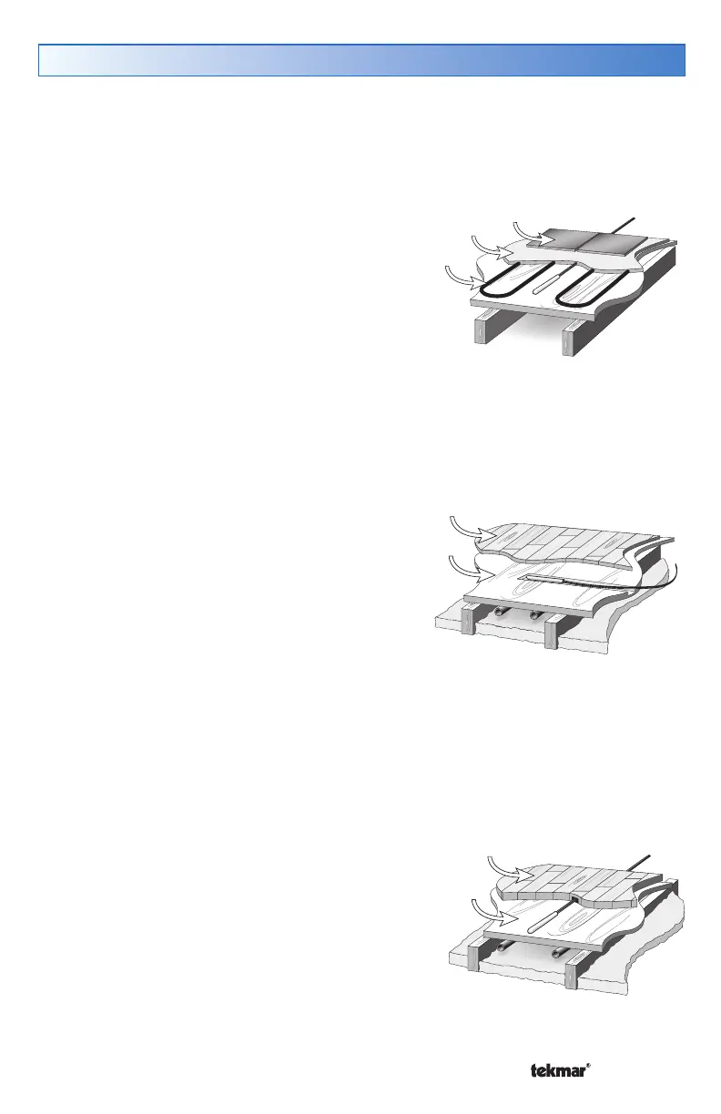
Thick Floor Coverings (greater than 3/8" (10 mm))
If a thick floor covering is to be installed directly to the subfloor, a groove 1/8" (4 mm) wide
by 1/16" (2 mm) deep can be cut into the back of the flooring material to accommodate
the wire for the sensor. Ensure that the sensor is located in such a position that the
attached wire is able to reach to a suitable junction location.
Splices under the floor covering should be avoided
to ensure trouble free operation. A groove 3/16"
(5 mm) wide by 3/16" (5 mm) deep by 1-3/4" (45
mm) long should be cut to accommodate the
sensor. The sensor should be located mid way
between the heating elements to ensure a proper
temperature reading.
If it is not practical to cut a groove in the surface
covering, follow the installation method used for
thin floor coverings.
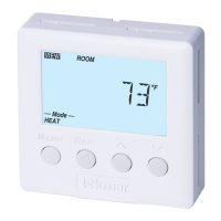
Slab Sensor 079 Installation
Thin-Set or Thin-Pour Applications
If the floor covering is to be installed over either a thin-set or thin-pour material of sufficient
depth, the 079 slab sensor can be placed directly into either the thin-set material or the
thin-pour material and covered over. Ensure
that the sensor is located in such a position that
the attached wire is able to reach to a suitable
junction location. Splices within the thin-set or
thin-pour should be avoided to ensure trouble
free operation. The sensor should be located
mid way between the heating elements to ensure
a proper temperature reading.
Tiles
Thin-set
Electric
Cables
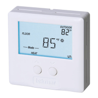
Thin Floor Coverings (less than 3/8" (10 mm))
If a thin floor covering is to be installed directly to the subfloor, a groove 1/8" (4 mm)
wide by 1/16" (2 mm) deep can be cut into the surface of the subfloor to accommodate
the wire for the sensor. Ensure that the sensor is located in such a position that the
attached wire is able to reach to a suitable junction
location. Splices under the floor covering should
be avoided to ensure trouble free operation.
A groove 3/16" (5 mm) wide by 3/16" (5 mm)
deep by 1-3/4" (45 mm) long should be cut to
accommodate the sensor. The sensor should be
located mid way between the heating elements to
ensure a proper temperature reading.
Hardwood
Subfloor
Hardwood
Subfloor
New Installations
--------------------------------------------------- ---------------------------------------------------