15
16
17
BW LIMIT
-When
pressed in, this button
sw
itch
limits the bandwidth
of
the vertical amplifier and the
A Trigger system
to
approximately 10 MHz. Button
must be pressed a second time to release it and
regain full
60
MHz bandwidth operation. Provides a
method for reducing interference from high-fre-
quency signals when viewing low-frequency
signals.
INVERT Switch
-Inverts
the Channel 2 display when
button is pressed
in.
Button must be pressed in a sec-
ond time
to
release it and regain a noninverted
display.
G
ND
Connector
-Provides
direct connection
to
the
instrument chassis ground.
SERIAL a
nd
Mod
Slots-
The SERIAL slot is im-
printed with the instrument's serial number. The Mod
slot contai
ns
the option number that is installed in the
instrument.
HORIZONTAL
Preparation for Use-
221
SA
Op
e
ra
to
rs
18A and B
SEC
/DIV Switches
-Used
to
select the
sweep speeds for the A and B Sweep generators
in
a
1-2-5 sequence.
To
obtain calibrated sweep speeds,
the A and B SEC/DIV Variable control must be in the
calibrated detent (fully clockwise).
A
SEC
/
DIV-
The calibrated sweep speed is
shown between the
two
black lines on the clear
plastic skirt. This switch also selects the delay time
for delayed-sweep operation when used
in
con-
junction with the B
DELAY
TIME POSITION
control.
B SEC/DIV- T
he
B
Sweep
speed is
set
by pulling
out
the DLY'D SWEEP kn
ob
and rotating it clock-
wise to a setting opposite the white line scribed on
the knob. The B Sweep circuit is used only for de-
layed-sweep operation.
19SEC/DIV Variable Control
-Provides
continuously
variable, uncalibrated A Sweep speeds
to
at least 2.5
times slow
er
than the calibrated setting.
It
extends the
slowest sweep speed
to
at
least 1.25 s per division.
20
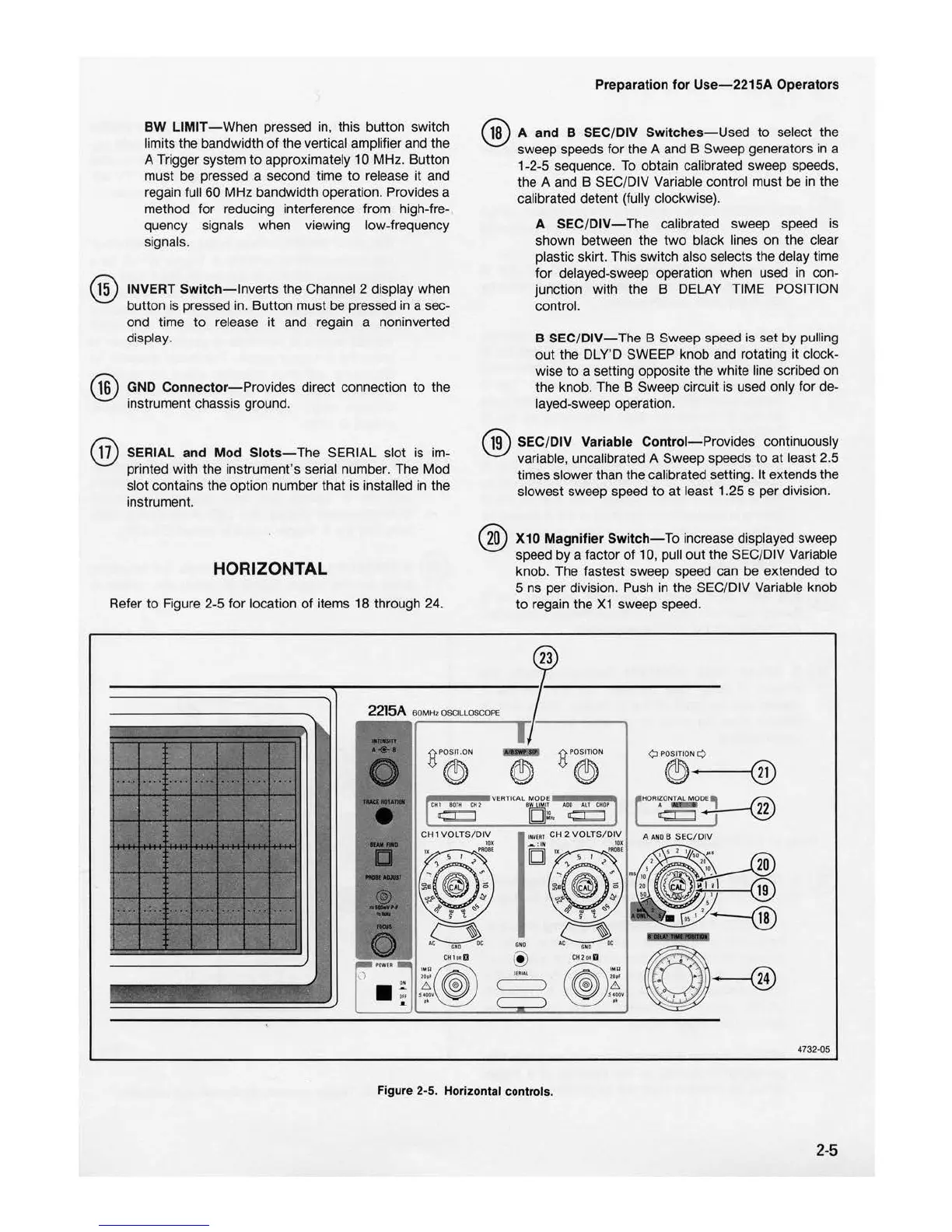
Refer
to
Figure 2-5 for location
of
items 18 through 2
4.
X10 Magnifier Switch
-To
increase displayed sweep
speed by a factor
of
10, pull out the SEC/DIV Variable
knob. The fastest sweep speed can be extended
to
5 ns per division. Push in the SEC/DIV Variable knob
to
regain the X1 sweep speed.
2215A
60
MHz
OSCILLOSCOPE
HORIZO
NTAL
11:::::r:::::J
4732
-0
5
Figure 2-5. Horizontal controls.
2-5

 Loading...


