28
SLO
PE
Switch
es-Selects
the slope
of
the signal
that triggers the sweep.
OUT
-When
button is released out, sweep is trig-
gered from the positive-going slope
of
the trigger
signal.
IN
-When
button is pressed in, sweep is triggered
from the negative-going slope
of
the trigger signal.
29 A SOURCE Switch
-Determines
the source
of
the
trigger signal that coupled
to
the input
ol
the A Trigger
circuit.
30
31
IN
T
-Permits
triggering on signals that are applied
to
the CH 1 OR X and CH 2 OR Y input connec-
tors. The source
of
the internal signal is selected by
the A
& B INT switch.
LINE-
The power-source waveform is the source
of
the trigger signal. This trigger source is useful
when vertical input signals are time related (multi-
ple
or
submultiple)
to
the frequency
of
the power-
input source voltage.
EXT
-Perm
its triggering on signals applied
to
the
EXT INPUT connector.
A&B
INT Switch
-Selects
the source
of
the internal
triggering signal when the A SOURCE switch is set
to
INT.
CH 1- The signal applied
to
the CH 1 OR X input
connector is the source
of
the trigger signal.
VERT MODE
-The
internal trigger source is deter-
mined
by
the signals selected
for
display by the
VERTICAL MODE switches. See Table 2-1
fo
r
VERT MODE trigger source.
CH
2- The signal applied
to
the
CH
2 OR Y input
connector is the source
of
the
tr
igger signal.
A EXT COUPLING
Swit
c
h-
Determines the method
used
to
couple external signals
to
the A TRIGGER
circuit from the EXT INPUT connector.
AC
-Signals
above 60 Hz are capacitively coupled
to
the input
of
the A Trigger circuit. Any de compo-
nents are blocked, and signals below 60 Hz are
attenuated.
Preparation for Use- 2215A Operators
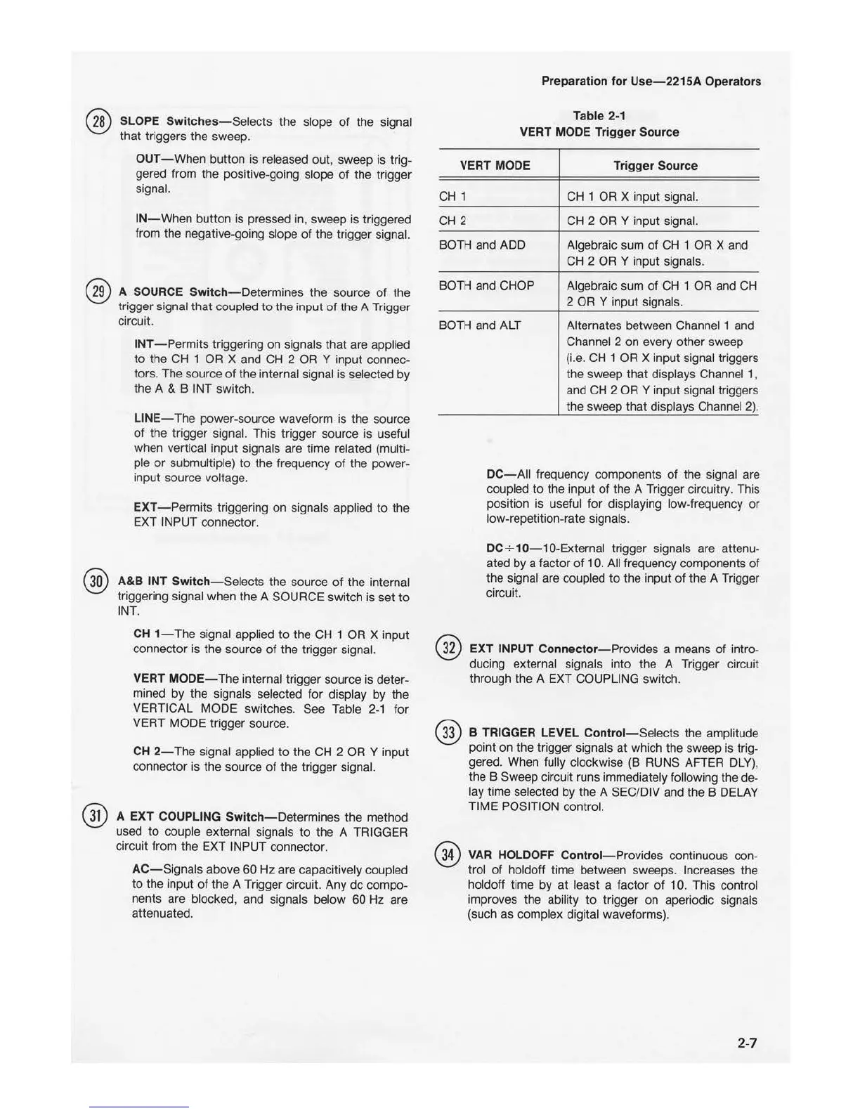
Table 2-1
VERT MODE Trigger Sour
ce
VERT MODE Trigger Sour
ce
CH
1
CH
1
OR
X input signa
l.
CH
2
CH
2
OR
Y input signal.
BOTH
and
ADD Algebraic sum
of
CH
1 OR X and
CH
2 OR Y input signals.
BOTH
and
CHOP Algebraic sum
of
CH 1 OR and
CH
2
OR
Y input signals.
BOTH
and ALT Alternates between Channel 1 and
Channel 2 on every other sweep
(i.e.
CH
1 OR X input signal triggers
the sweep that displays Channel 1,
and CH 2
OR
Y input signal triggers
the sweep th
at
displays Channel 2).
32
33
34
D
C-All
frequency components of the signal are
coupled
to
the input
of
the A Trigger circuitry. This
position is useful for displaying low-frequency
or
low-repetition-rate signals.
DC÷
10-
10-External trigger signals are attenu-
ated by a factor
of
10. All frequency components of
the signal are coupled
to
the input
of
the A Trigger
circuit.
EXT INPUT Connector
-P
rovides a means
of
intro-
ducing external signals i
nto
the A Trigger circuit
through the A EXT COUPLING switch.
B TRIGGER LEVEL Control
-Selects
the amplitude
poi
nt
on
th
e trigger signals at which the sweep is trig-
ger
ed.
When fully clockwise (B RUNS AFT
ER
DLY),
the B Sweep circuit runs immediately following the de-
lay time selected by the A SEC/DIV and the B
DELAY
TIME POSITION control.
VAR
HOLDOFF Control
-Provides
continuous con-
trol
of
holdoff time between sweeps. Increases the
holdoff ti
me
by
at
least a factor
of
10. This control
improves the ability
to
trigger on aperiodic signals
(such as complex digital
wa
veforms).
2-7

 Loading...


