t
NEGATIVE
REFERENCE
LINE
-----------
--
--
J
VERTICAL
DEFLECTION
............... .
-----
,----
POSITIVE
REFERENCE
LINE
MEASURE
POSITIVE
AMP
LI
TUDE
TO
OR
NEGATIVE
AMPLI
T
UDE
TO
4732·08
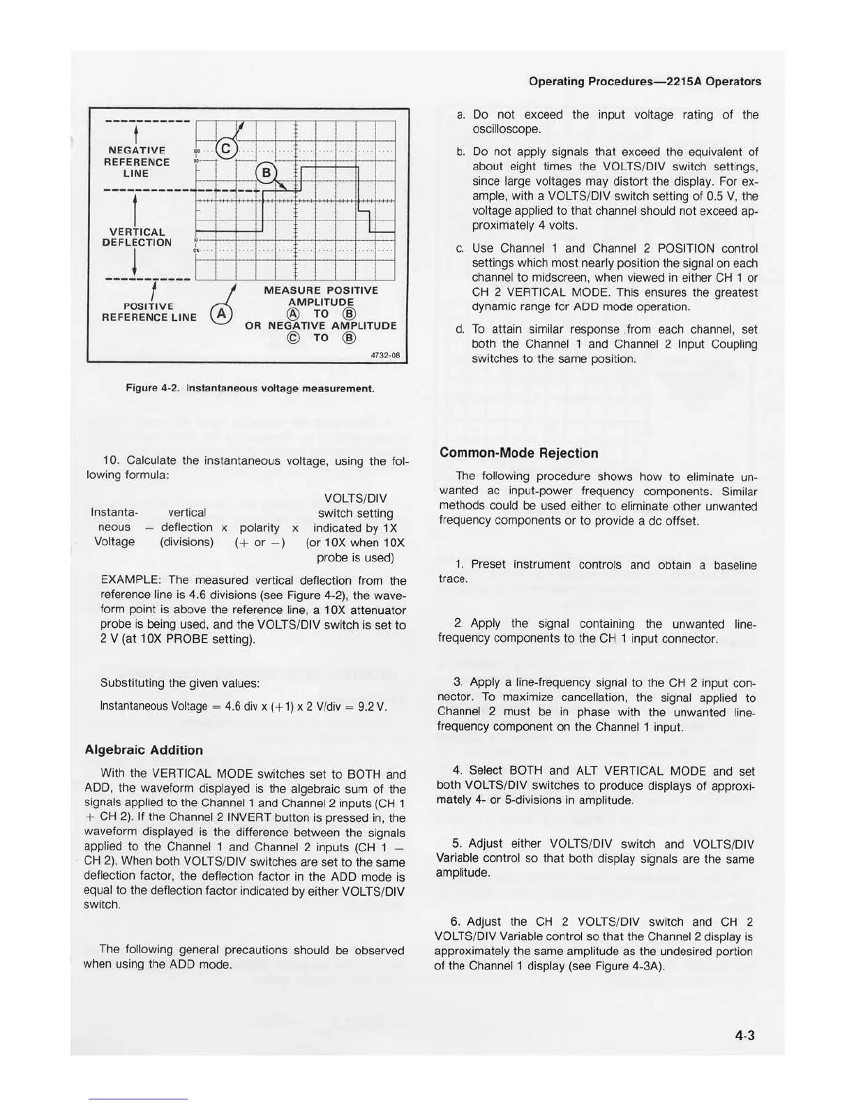
Figure
4-2
. Instantaneous vol
tage
meas
urement.
10. Calculate the instantaneous voltage, using the fol-
lowing formula:
lnstanta-
neous
Voltage
vertical
deflection x polarity x
(divisions) (
+
or
- )
VOLTS/DIV
switch setting
indicated by 1 X
(or 1
OX
when 1
OX
probe is used)
EXAMPLE: The measured vertical deflection from the
reference line is 4.6 divisions (see Figure 4-2), the wave-
form point is above the reference line, a 1
OX
attenuator
probe is be
in
g used, and
th
e VOLTS/DIV switch is set
to
2 V (at 1
OX
PROBE setting).
Substituting the given values:
I
nstantaneous
Voltage
=
4.6
div x ( +
1)
x 2 V/
div
=
9.2
V.
Algebraic Addition
With the VERTICAL MODE switches set
to
BOTH and
ADD, the waveform displayed is the algebraic sum
of
the
signals applied
to
the Channel 1 and Channel 2 inputs (CH 1
+
CH
2).
If
the Channel 2 INVERT button is pressed in, the
waveform displayed is the difference between the signals
applied
to
the Channel 1 and Channel 2 inputs (CH 1 -
CH
2).
When both VOLTS/DIV switches are set
to
the same
deflection factor, the deflection factor in the ADD mode is
equal
to
the deflection factor indicated by either VOLTS/DIV
switch.
The following general precautions should be observed
when using the ADD mode.
Operating Procedures
-22
15A Operators
a.
Do
not
exceed the input voltage rating
of
the
oscilloscope.
b.
Do not apply signals that exceed the equivalent of
about eight times the VOLTS/DIV switch settings,
since large voltages may distort the display. For ex-
ample, with a VOLTS/DIV switch setti
ng
of
0.5 V, the
voltage app
li
ed
to
that channel should not exceed ap-
proximately 4 volts.
c.
Use Channel 1 and Channel 2 POSITION control
settings which most nearly position the signal on each
channel
to
midscreen, when viewed in either
CH
1
or
CH 2 VERTICAL MODE. This ensures the greatest
dynamic range for ADD mode operation.
d.
To
attain similar response from each channel, set
both the Channel 1 and Channel 2 Input Coupli
ng
switches
to
the same position.
Common-Mode Rejection
The following procedure shows how
to
eliminate
un
-
wanted ac input-power frequency components. Similar
methods could be used either
to
eliminate other unwanted
frequency components
or
to provide a de offset.
1 . Preset instrument controls and obtain a baseline
trace.
2. Apply the signal containing the unwanted line-
frequency components
to
the
CH
1 input connector.
3. Apply a line-frequency signal
to
the CH 2 input con-
nector.
To
maximize cancellation, the signal applied
to
Channel 2 must be in phase with the unwanted line-
frequency component on the Channel 1 input.
4. Select BOTH and ALT VERTICAL MODE
and
set
both VOLTS/DIV switches
to
produce displays
of
approxi-
mately 4-
or
5-divisions in amplitude.
5. Adjust either VOLTS/DIV switch
and
VOLTS/DIV
Variable control so that both display signals are the same
amplitude.
6. Adjust the
CH
2 VOLTS/DIV switch and
CH
2
VOLTS/DIV Variable control so that the Channel 2 display is
approximately the same amplitude as the undesired portion
of
the Channel 1 display (see Figure 4-3A).
4-3

 Loading...


