I
NTENS
I
FIED
/
ZONE
A
TRACE
B
TRACE
r
-
ALT
HORIZ
DISPLAY
\
VERTICAL
REFERENCE
LINE
C4207-23
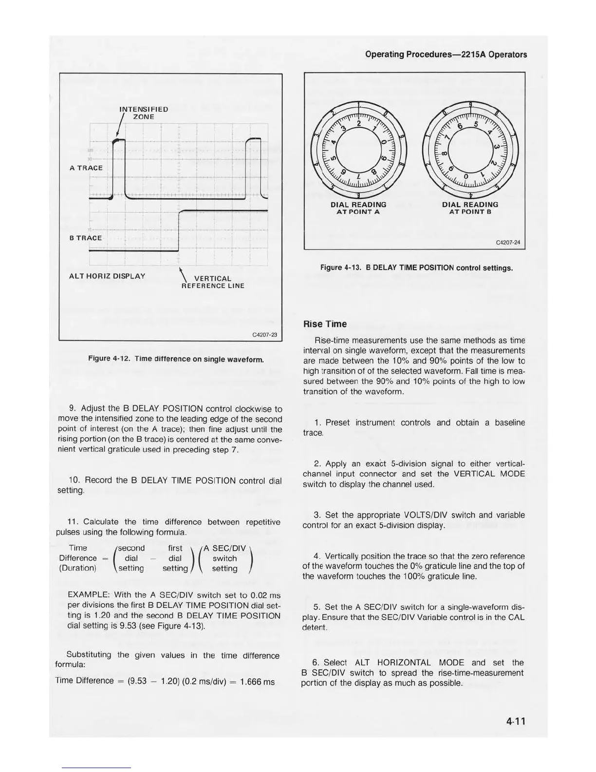
Figure
4-12.
Time
difference
on
single
waveform.
9. Adjust the B DELAY POSITION control clockwise
to
move the intensified zone
to
the leading edge
of
the second
point
of
interest (on the A trace); then fine adjust until the
rising portion
(on
the B trace) is centered at the same conve-
nient vertical graticule used in preceding step
7.
10. Record the B DELAY TIME POSITION control dial
setting.
11
. Calculate the time difference between repetitive
pulses using the following formula.
Time (second first )
(A
SEC/
DIV)
Difference = dial - dial switch
(Duration) setting setting setting
EXAMPLE: With the A SEC/DIV switch set
to
0.02 ms
per divisions the first B DELAY TIME POSITION dial set-
ting is 1.20 and the second B DELAY TIME POSITION
dial setting is 9.53 (see Figure 4-13).
Substituting the given values
in
the time difference
formula:
Time Difference = (9.53 - 1.20) (0.2 ms/div) = 1.666 ms
Operating Proce
dures
-22
15A
Operators
DIAL
READING
AT
PO
IN
T A
DIAL
READIN
G
AT
POINT
B
C4207-24
Figure 4-13. B DELAY TIME POSITION
control
setti
ngs
.
Rise Time
Rise-time measurements use the same methods as time
interval on single waveform, except that the measurements
are made between the 1 0% and 90% points
of
the low
to
high transition
of of
the selected waveform. Fall ti
me
is mea-
sured between the 90% and 10% points
of
the high
to
low
transition of the waveform.
1 . Preset instrument controls and obtain a baseline
trace.
2. Apply an exact 5-division signal
to
either vertical-
channel input connector and set the VERTICAL MODE
switch
to
display the channel used.
3. Set the appropriate VOLTS/DIV switch and variable
control for an exact 5-division display.
4. Vertically position the trace so that the zero reference
of
the waveform touches the 0% graticule line and the top
of
the waveform touches the 100% graticule line.
5.
Set the A SEC/DIV switch
for
a single-waveform dis-
play. Ensure that the
SEC
/DIV Variable control is
in
the CAL
detent.
6. Select
ALT
HORIZONTAL MODE and set the
B
SEC
/DIV switch
to
spread the rise-time-measurement
portion
of
the display as much as possible.
4-11

 Loading...


