Operating Procedur
es-22
15A Operators
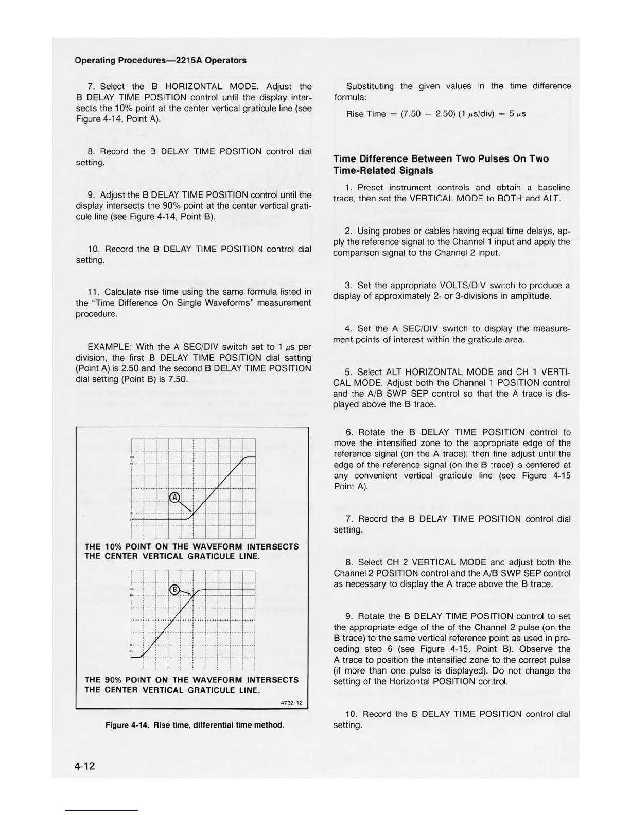
7. Select the B HORIZONTAL MODE. Adjust the
B
DELAY
TIME POSITION control until the display inter-
sec
ts the 10% point
at
th
e center vertical graticule line (see
Figure 4-14, Point
A).
8. Record the B DELAY TIME POSITION control dial
setting.
9.
Adjust the B DELAY TIME POSITION control until the
display intersects the 90% point
at
the center vertical grati-
cule line
(see
Figure 4
-1
4, Point B).
10. Record the B
DELAY
TIME POSITION control dial
se
tt
ing.
11. Calculate rise time using the same formula listed in
the "Time Difference On Single Waveforms" measurement
procedure.
EXAMPLE: With the A SEC/DIV
sw
itch set to 1
µS
per
division, the first B DELAY TIME POSITION dial setting
(Point
A)
is 2.50 and the second B DELAY TIME POSITION
dial setting (Point
B)
is 7.50.
V
::::!::::
-~~
i ·
:··
..
V
..
_,..._,_....,
....
,
..........
~v
._.
··-~·-
:··
i
...
····
..
l==-
_
THE
10
%
POINT
ON
THE
WAVEFORM
INTERSE
CTS
THE CENTER VERTICAL GRATICULE LIN
E.
! .
...!
....
j
....
Ji
····
=
···l··
·+·+
B -
--
...
-+-
.
-+--+-
-i
I·
·i· ··i
··I·
....
·I
..
•···•
1
•
•••!••••
1
•
•••1•••1••••J••••1••••1••
••
1••
••·
. ! : : t
THE
90
%
POINT
ON
THE
WAVEFORM
INTERSECTS
THE CENTER VERTICAL GRATICULE LINE.
4732-
12
Figure 4-14. Rise tim
e,
differential time method.
4-
12
Substituting the given values in the time difference
formula:
Rise Time =
(7
.50 - 2.50)
(1
µs/div) = 5
µS
Time Difference Between Two Pulses
On
Two
Time-Related Signals
1 . Preset instrument controls and obtain a baseline
trace, then set the VERTICAL MODE
to
BOTH and ALT.
2. Using probes
or
cables having equal time delays, ap-
ply the reference signal
to
the Channel 1 input and apply the
comparison signal
to
the Channel 2 input.
3. Set the appropriate VOLTS/DIV switch
to
produce a
display of approximately 2-
or
3-divisions in amplitude.
4. Set the A SEC/DIV switch
to
display the measure-
ment points
of
interest within the graticule area.
5. Select ALT HORIZONTAL MODE and
CH
1 VERTI-
CAL MODE. Adjust both the Channel 1 POSITION control
and the A/B SWP SEP control so that the A trace is dis-
played above the B trace.
6. Rotate the B DELAY TIME POSITION con
tr
ol
to
move the intensified zone
to
the appropriate edge
of
the
reference signal (on the A trace); then fine adjust until the
edge
of
the reference signal (on the B trace) is centered at
any convenient vertical graticule line (see Figure 4-15
Poi
nt
A).
7. Record the B DEL
AY
TIME POSITION control dial
setting.
8. Select
CH
2 VERTICAL MODE and ad
ju
st both the
Channel 2 POSITION control and the A/B SWP SEP control
as necessary
to
display the A trace above the B trace.
9. Rotate the B DELAY TIME POSITION control
to
set
the appropriate edge
of
the of the Channel 2 pulse
(on
the
B trace)
to
the same vertical reference point as used in pre-
ceding step 6 (see Figure 4-15, Point B). Observe the
A trace
to
position the intensi
fied
zone
to
the
co
rrect pulse
(if more than one pulse is displayed). Do
not
change the
setting of the Horizontal POSITION contro
l.
10. Record the B DELAY TIME POSITION control di
al
setting.

 Loading...


