Section
3-
2215A Operators
OPERATORS FAMILIARIZATION
GENERAL OPERATING INFORMATION
GRATICULE
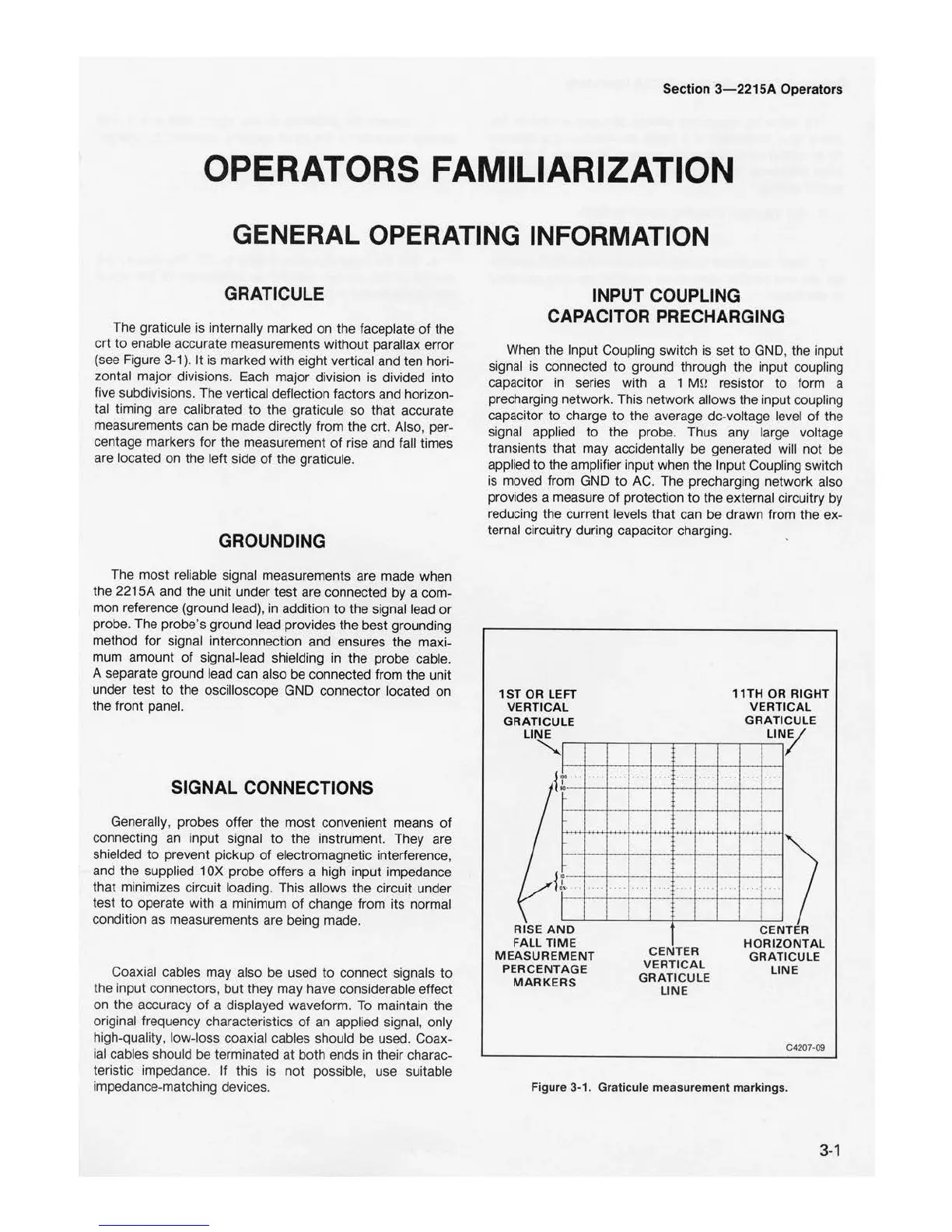
The graticule is internally marked on the faceplate
of
the
crt
to
enable accurate measurements without parallax error
(see Figure
3-1
).
It
is marked with eight vertical and ten hori-
zontal major divisions. Each major division is divided into
five subdivisions. The vertical deflection factors and horizon-
tal timing are calibrated
to
the graticule so that accurate
measurements can be made directly from the crt. Also, per-
centage markers
for
the measurement
of
rise and fall times
are located on the left side
of
the graticule.
GROUNDING
The most reliable signal measurements are made when
the 2215A and the unit under test are connected
by
a com-
mon reference (ground lead), in addition
to
the signal lead
or
probe. The probe's ground lead provides the best grounding
method for signal interconnection and ensures the maxi-
mum amount
of
signal-lead shielding in the probe cable.
A separate ground lead can also be connected from the unit
under test
to
the oscilloscope GND connector located
on
the front panel.
SIGNAL CONNECTIONS
Generally, probes offer the most convenient means
of
connecting an input signal
to
the instrument. They are
shielded
to
prevent pickup
of
electromagnetic interference,
and the supplied 1
OX
probe offers a high input impedance
that minimizes circuit loading. This allows the circuit under
test
to
operate wi
th
a minimum
of
change from its normal
condition as measurements are being made.
Coaxial cables may also be used
to
connect signals
to
the input connectors, but they may have considerable effect
on the accuracy
of
a displayed waveform.
To
maintain the
original frequency characteristics
of
an applied signal, only
high-quali
ty
, low-loss coaxial cables should be used. Coax-
ial cables should be terminated
at
both ends in their charac-
teristic impedance.
If
this is
not
possible, use suitable
impedance-matching devices.
INPUT COUPLING
CAPACITOR PRECHARGING
When the Input Coupling switch is set
to
GND, the input
signal is connected
to
ground through the input coupling
capacitor in series with a 1 þÿM©resistor
to
form a
precharging network. This network allows the input coupling
capacitor
to
charge
to
the average de-voltage level of the
signal applied
to
the probe. Thus any large voltage
transients that may accidentally be generated will not be
applied
to
the amplifier input when the Input Coupli
ng
switch
is moved from GND
to
AC. The precharging network also
provides a measure
of
protection
to
the external circuitry by
reducing the current levels that can be drawn from the ex-
ternal circuitry during capacitor charging.
1
ST
OR
LEFT
11TH
OR RIG
HT
VERT
ICA
L
VE
RTI
CAL
GR
ATICULE
GRAT
ICU
LE
.. ·_·
-j
""
.....
..
.
I
CENTER
RISE
AND
FA
LL
TIME
MEAS
U
REMEN
T
PERCENTAGE
MARKERS
CENTER
VERT
ICAL
GRATICULE
LINE
HORIZONTA
L
GRA
T
ICULE
LINE
C4207-
09
Figure
3-1. Graticule
measurement
markings.
3-1

 Loading...


