EasyManua.ls Logo

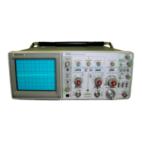
Tektronix 2235 - OSCILLOSCOPE DISPLAYS; INTRODUCTION; BASELINE TRACE; Horizontal

Tektronix 2235
53 pages
To Next Page IconTo Next Page
To Previous Page IconTo Previous Page
Loading...
G
ENER
A
L
O
PER
ATI
N
G
I
NF
O
RM
ATIO
N
T
h
e
g
r
atic
u
le is
internally
mar
ked
on
t
h
e
faceplate
of
t
he
crt
to
ena
b
le
accu
rate
meas
u
reme
n
ts
wit
h
o
u
t
pa
r
allax
error
(see
Figure
3-1)
.
It
is
mar
ked
wit
h
eig
h
t
vertical
a
n
d
te
n ho
r
i-
zontal
ma
j
or
divisions
.
Eac
h
ma
j
o
r
division
is divi
ded
into
five
su
b
divisions
.
T
he
vertical
deflectio
n
factors
and
h
orizon-
tal
timi
ng
a
r
e
cali
br
ated
to
t
he
gratic
u
le
so
t
h
at
accu
r
ate
meas
u
reme
n
ts
ca
n be
ma
de
di
r
ectly
from
t
he
crt
.
Also,
p
e
r-
cen
tage
mar
k
ers
for
t
he
measureme
n
t
of
rise
an
d
fall
times
are
located
on
t
he
left
si
de
of
t
he
graticule
.
G
R
OUN
DI
N
G
T
h
e
most
r
eliable
signal
measureme
n
ts
a
r
e
made
w
hen
t
h
is
instr
u
me
n
t
a
nd
t h
e
unit
under
test
are
connected
by α
common
reference (grou
n
d
lead),
i
n
addition
to
t
he
signal
lea
d
o
r
p
robe
.
T
he pro
b
e's
gro
un
d
lea
d
p
rovides
t
he
b
est
grou
n
di
ng
met
h
od
for
sig
n
al
interco
n
nectio
n
and
e
n
sures
t
he
maximum
amount
of
signal-lea
d
s
h
iel
d
ing
in
t
he
p
robe
cable
.
Α
separate
grou
n
d
lea
d
can
also
b
e connected from
t
he
unit
under
test to
t
he
oscillosco
pe
G
N
D
connector
lo-
cated on
t
he
front
p
an
el
.
SIG
N
A
L
CO
NNE
CTIO
N
S
Generally,
pro
b
es
offer
t
h
e
most
convenient
means
of
connecting
an
input
signal
to
t
h
e
inst
r
ument
.
T
h
ey
are
sh
ielded
to
pr
event p
ic
kup
of
electromag
n
etic
i
n
terference,
and
t
he supp
lie
d
10
Χ
p
robe
offers
α
hig
h
in
p
ut
imp
eda
nce
t
h
at
minimizes
circuit
loading
.
T
h
is
allows
t
h
e
circ
u
it
un
der
test
to
op
erate
wit
h α
minim
u
m
of
c
h
ange
fr
om
its
normal
condition
as
measurements
are
b
eing
made
.
Coaxial
ca
b
les
may
also
be used
to
connect
signals
to
t
h
e
in
p
ut
connectors,
bu
t
t
hey
may
h
ave
considera
b
le
effect
on
t
he accuracy
of
α
d
is
p
layed
waveform
.
To
main
tai
n
t
he
origi
n
al
fre
q
uency
ch
aracteristics
of
an
ap
p
lied
signal,
o
n
ly
h
ig
h
-quality,
low-loss
coaxial
cables
s
h
o
u
l
d
b
e
u
sed
.
Coax-
ial
cables
s
hou
l
d b
e
terminated
at
both ends
in
t
h
eir
c
h
arac-
te
r
istic
im
p
edance
.
If
t h
is
is
not
p ossible,
use
suita
b
le
impe
d
a
nce-match
i
ng
devices
.
Section
3-2235
ΑΝ
/
U
S
M
-488
Ope
r
ato
r
s
O
PER
ATI
N
G
CO
N
SID
ER
ATIO
N
S
G
R
ATIC
ULE
I
NPU
T
CO
UPL
I
N
G
CA
P
ACITO
R
PRE
C
H
A
R
GI
N
G
Wh
e
n
t
he
In
p
ut
Cou
p
ling
switc
h
is
set
to
G
N
D,
t
he
i
np
ut
signal
is
co
nn
ecte
d
to
ground
t
h
ro
ugh
t
he
inp
u t
cou
p
li
ng
capacitor
in
series
wit
h
α
1
ΜΩ
resistor
to
form
α
p
r
ec
h
arging
network
.
T
h
is
network
allows
t
h
e
i
np
ut
cou
p
ling
cap
acitor
to
c
ha
r
ge
to
t
he
average
d
c-voltage
level of
t
h
e
signal applie
d
to
t
he
pr
obe
.
T
h
us
any
large
voltage
transients
t
h
at
may
acci
d
entally b
e
ge
n
e
r
ated
will
n
ot
be
app
lied
to
t
he
am
p
lifier
in
pu
t
when
t
h
e
Inp
u
t
Co
up
li
ng
switc
h
is
move
d
from
G
ND
to
AC
.
T
h
e
p
r
ec
h
arging
networ
k
also
p
rovides
α
measure
of
protectio
n
to
t
h
e
exte
rn
al
ci
r
cuitry
by
r
educing
t
he
curre
n
t
levels
t
h
at
can
b
ed
r
aw
n from
t
he
ex-
ter
n
al
ci
r
cuit
r
y
duri
ng
capacitor
c
h
arging
.
1ST
O
R
LEF
T
11TH
O
R
R
IG
HT
V
ERTICA
L
VER
TICA
L
GR
ATIC
ULE
G
R
ATIC
ULE
L
I
NE
L
I
NE
/
R
IS
E
A
N
D
C
EN
T
ER
F
A
LL
TIME
T
ER
H
O
R
IZO
N
TA
L
C
EN
ME
AS
UREMEN
T
GR
ATIC
ULE
PER
C
EN
TAG
E
VER
TICA
L
L
I
NE
MA
RKER
S
G
R
ATIC
ULE
L
I
NE
F
igure
3-1
.
G
r
atic
u
le
meas
ureme
n t
ma
rk
i
n
gs
.
c42a-09

Table of Contents

Other manuals for Tektronix 2235

Related product manuals