Controls, Connectors, and Indicators
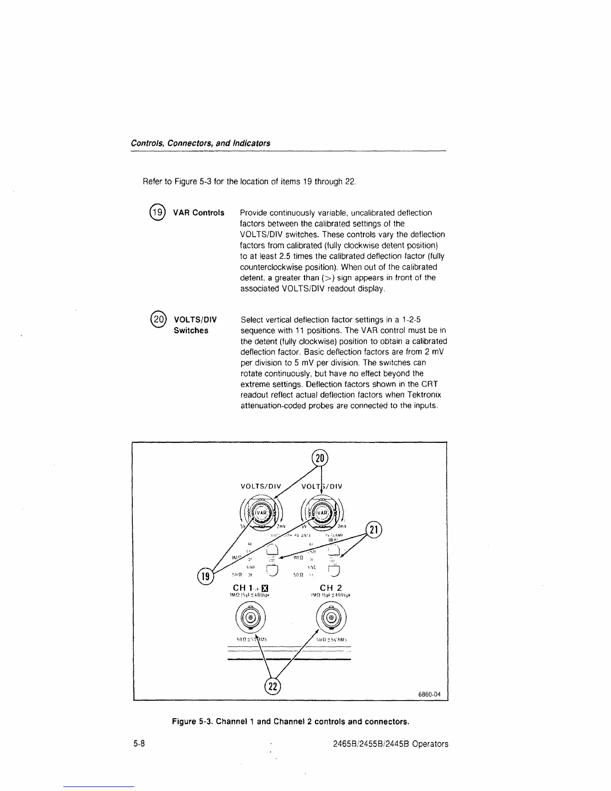
Refer to Figure 5-3 for the location of items 19 through 22.
19
J
VAR Controls Provide continuously variable, uncalibrated deflection
factors between the calibrated settings of the
VOLTS/DIV switches. These controls vary the deflection
factors from calibrated (fully clockwise detent position)
to at least 2.5 times the calibrated deflection factor (fully
counterclockwise position). When out of the calibrated
detent, a greater than (>) sign appears in front of the
associated VOLTS/DIV readout display.
20) VOLTS/DIV Select vertical deflection factor settings in a 1-2-5
Switches sequence with 11 positions. The VAR control must be in
the detent (fully clockwise) position to obtain a calibrated
deflection factor. Basic deflection factors are from 2 mV
per division to 5 mV per division. The switches can
rotate continuously, but have no effect beyond the
extreme settings. Deflection factors shown in the CRT
readout reflect actual deflection factors when Tektronix
attenuation-coded probes are connected to the inputs.
6860-04
5-8
Figure 5-3. Channel 1 and Channel 2 controls and connectors.
2465B/2455B/2445B Operators
 Loading...


