Applications
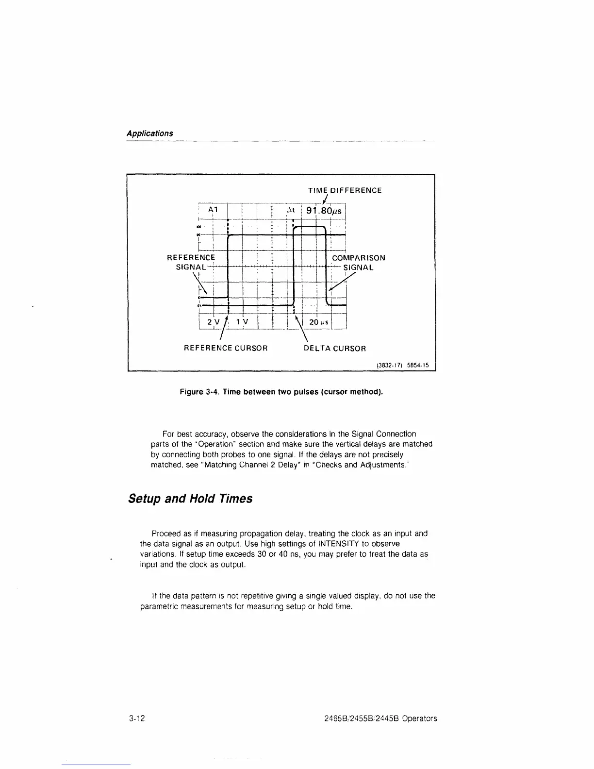
TIME DIFFERENCE
/
1
A1
i !
00
I
r
!
REFERENCE
SIGNAL !'"
X
I
T
j
!
■"
■
■ .
At
j 91
: = !
! •=
■■:"{■
2 V / IV
l
1
I
J
/
REFERENCE CURSOR
'—
.80/ys
'
j
1
i
COMPARISON
"'"r'"'"*
SIGNAL
; i/
i
u
: ! ! I
\
i
20
ps
\
DELTA CURSOR
(3832-17) 5854-15
Figure 3-4. Time between two pulses (cursor method).
For best accuracy, observe the considerations in the Signal Connection
parts of the "Operation" section and make sure the vertical delays are matched
by connecting both probes to one signal. If the delays are not precisely
matched,
see "Matching Channel 2 Delay" in "Checks and Adjustments."
Setup and
Hold Times
Proceed as if measuring propagation delay, treating the clock as an input and
the data signal as an output. Use high settings of INTENSITY to observe
variations. If setup time exceeds 30 or 40 ns, you may prefer to treat the data as
input and the clock as output.
If the data pattern is not repetitive giving a single valued display, do not use the
parametric measurements for measuring setup or hold time.
3-12
2465B/2455B/2445B Operators

 Loading...


