General Information
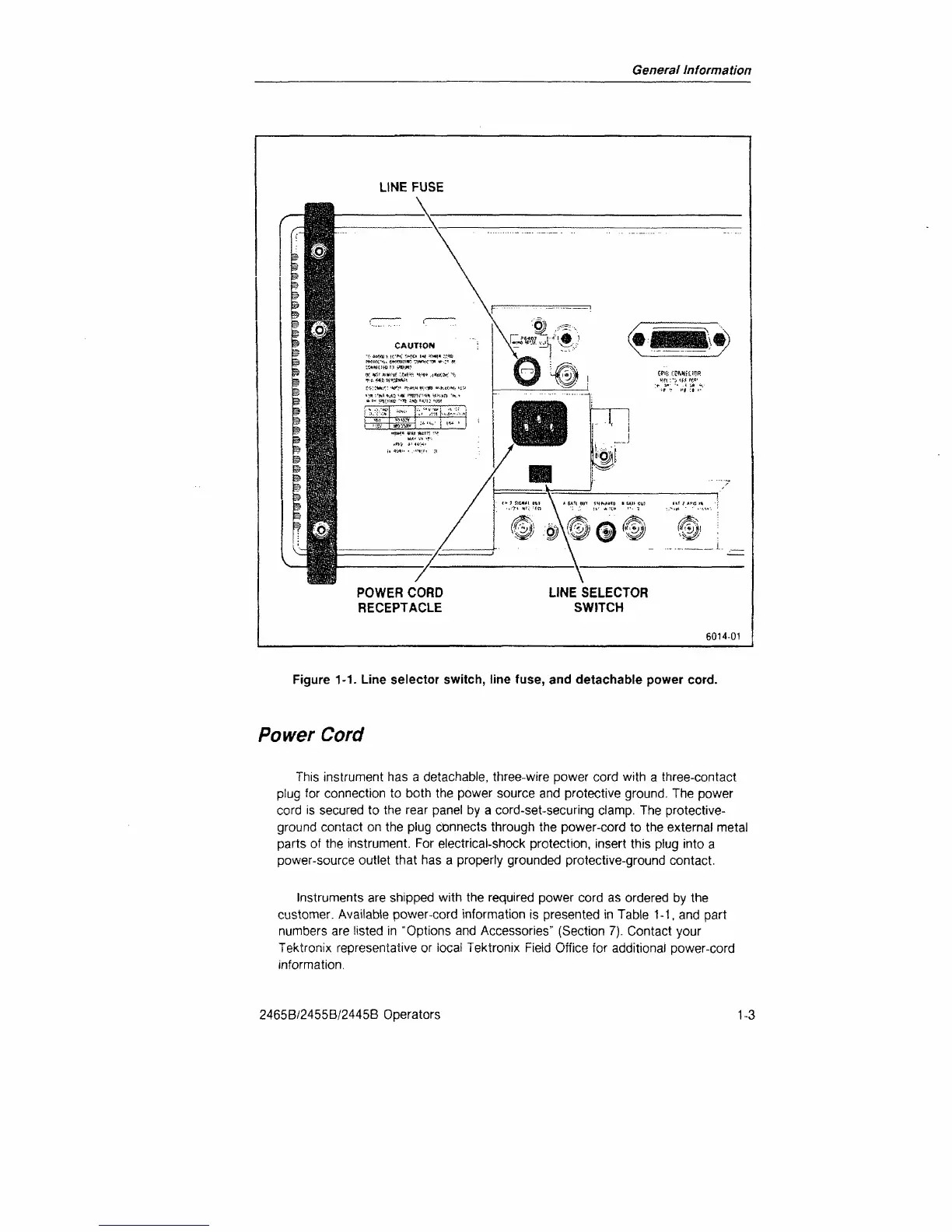
Figure 1-1. Line selector switch, line fuse, and detachable power cord.
Power
Cord
This instrument has a detachable, three-wire power cord with a three-contact
plug for connection to both the power source and protective ground. The power
cord is secured to the rear panel by a cord-set-securing clamp. The protective-
ground contact on the plug connects through the power-cord to the external metal
parts of the instrument. For electrical-shock protection, insert this plug into a
power-source outlet that has a properly grounded protective-ground contact.
Instruments are shipped with the required power cord as ordered by the
customer. Available power-cord information is presented in Table 1-1, and part
numbers are listed in "Options and Accessories" (Section 7). Contact your
Tektronix representative or iocai Tektronix Fieid Office for additional power-cord
information.
2465B/2455B/2445B Operators
1-3

 Loading...


