Controls, Connectors, and Indicators
NOTE
The calibrator signal changes phase during trigger
holdoff.
This does not affect the accuracy of the
calibrator signai that is present during a sweep.
However, if the CALIBRATOR signal is used with
other instruments, the sweep of the instrument
must be shut off. If it is not, the signal will appear
to jitter and will give false (low) frequency counts.
The sweep of the instrument is easily shut off by
setting TRIGGER MODE to SGL SEQ.
L
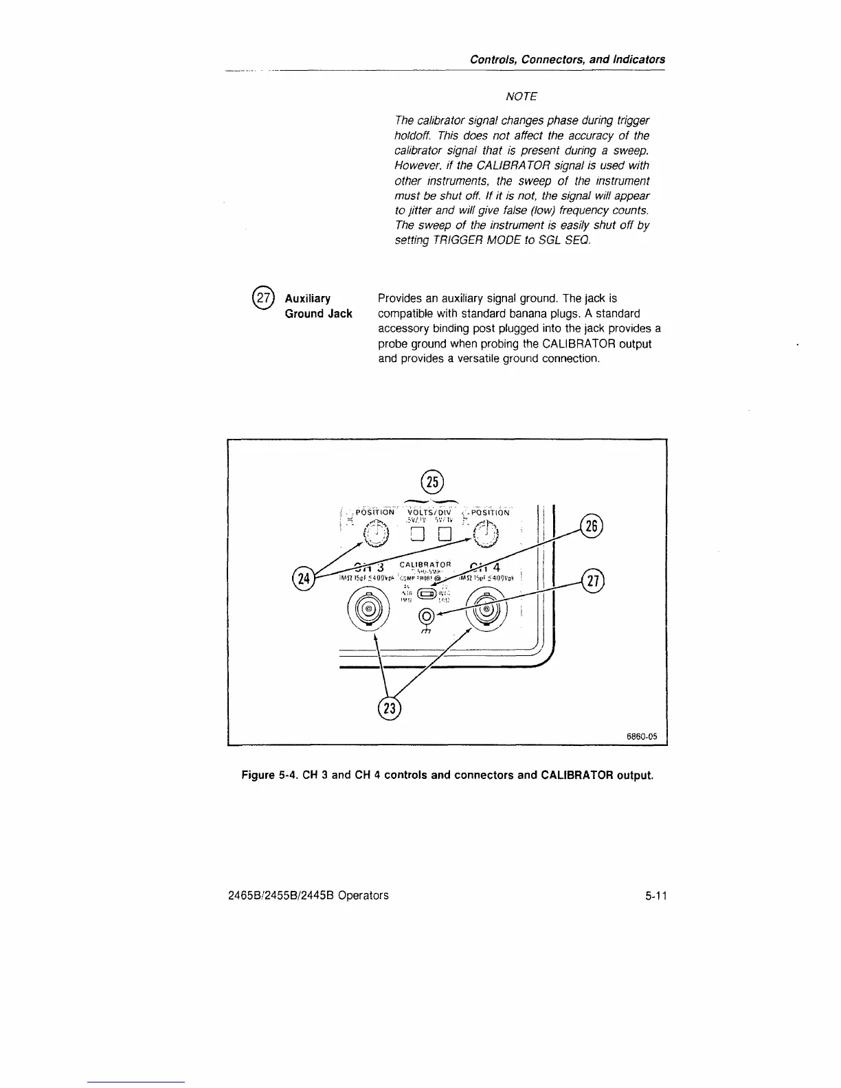
27) Auxiliary Provides an auxiliary signal ground. The jack is
Ground Jack compatible with standard banana plugs. A standard
accessory binding post plugged into the jack provides a
probe ground when probing the CALIBRATOR output
and provides a versatile ground connection.
6860-05
Figure 5-4. CH 3 and CH 4 controls and connectors and CALIBRATOR output.
2465B/2455B/2445B Operators
5-11

 Loading...


