Controls,
Connectors,
and Indicators
TRACK/INDEP Selects either the Tracking or Independent mode for the
Button A REF OR DLY POS control. In the Tracking mode,
rotating the A REF OR DLY POS control changes both
delays or both cursors equally until the limit of either
is reached.
In the Indep mode, A REF OR DLY POS affects only the
reference deiay or cursor. In either Tracking or
Independent mode, the A control moves only the
A cursor.
6860-06
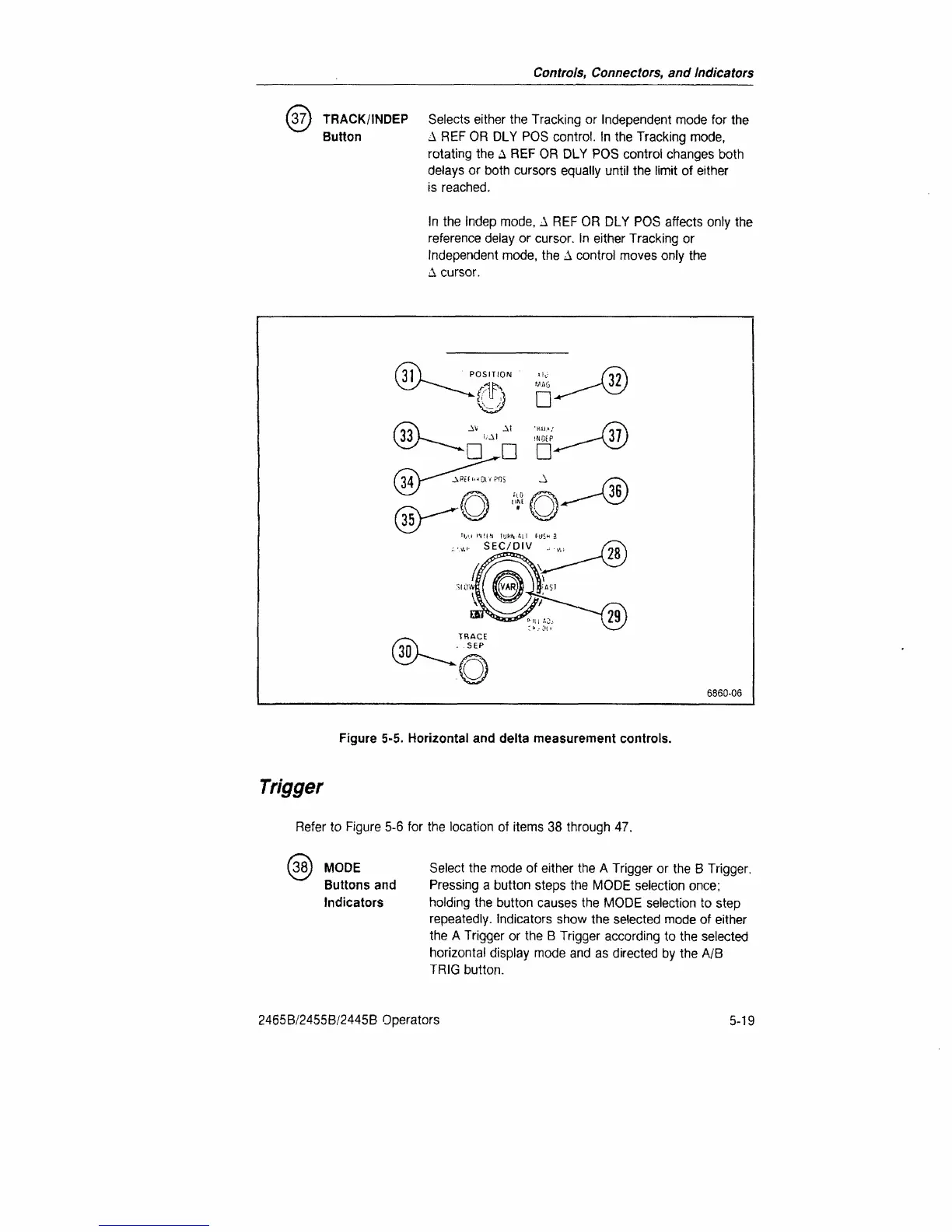
Figure 5-5. Horizontal and delta measurement controls.
Trigger
Refer to Figure 5-6 for the location of items 38 through 47.
38) MODE
Buttons and
Indicators
Select the mode of either the A Trigger or the B Trigger.
Pressing a button steps the MODE selection once;
holding the button causes the MODE selection to step
repeatedly. Indicators show the selected mode of either
the A Trigger or the B Trigger according to the selected
horizontal display mode and as directed by the A/B
TRIG button.
2465B/2455B/2445B Operators
5-19
 Loading...


