Controls, Connectors, and Indicators
69} REF DISPLAY
/REF SET
REF
DISPLAY
Displays or sets a reference measurement.
Shows the present reference value. If no reference
has been set, the display will show 0.
REF SET
70) HIGH and
LOW
Connectors
©
Fuse
Initializes the reference value to the present display.
All subsequent measurements will be displayed with
this reference value subtracted from them. If no
measurement is displayed, or if the present
measurement is out of range, REF SET has
no effect.
When a measurement has a reference value
subtracted from it, the display includes a A symbol.
With dBV or dBm, the reference takes the place of
V
ref
. Selecting a new DMM function or turning off
power clears the reference. The reference is retained
if another instrument function, such as At, displaces
the DMM measurement and then the same DMM
measurement is selected again.
Provide high-impedance, floating inputs to the DMM. For
DC and resistance measurements, the upper, red
terminal is positive and the lower, black input
is negative.
Excessive input in a current-measuring mode may open
the input fuse. If the fuse opens, none of the DMM
functions will work. To replace the fuse, turn off the
instrument, remove the DMM probes, and unscrew the
fuse holder. Replace the fuse with a 1.5 A, fast acting,
3AG fuse. (The fuse holder will accept a 5 X 25 mm
fuse,
with the appropriate cap substituted for the
original.) Then, replace the probes and turn on the
instrument.
ODD 3 J 3 D '2
3 3 3 3
(nT-'O
1
Tektronix
2465BOOOMHZ
« "'V:",.,.
i f! 1 1 1 1 i \ \ I I II
1
686009
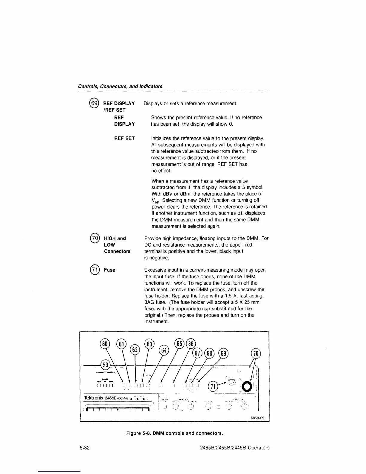
Figure 5-8. DMM controls and connectors.
5-32 2465B/2455B/2445B Operators

 Loading...


