Performance Characteristics
Table 6-1 (cont)
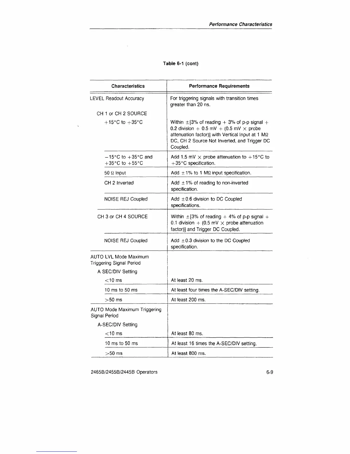
Characteristics
LEVEL Readout Accuracy
CH 1 or CH 2 SOURCE
+ 15°Cto +35°C
-15°C to +35°C and
+35°Cto + 55°C
50
Q
input
CH 2 Inverted
NOISE REJ Coupled
CH 3 or CH 4 SOURCE
NOISE REJ Coupled
AUTO LVL Mode Maximum
Triggering Signai Period
A SEC/DIV Setting
<10 ms
10 ms to 50 ms
>50 ms
AUTO Mode Maximum Triggering
Signal Period
A-SEC/DIV Setting
<10 ms
10 ms to 50 ms
>50 ms
Performance Requirements
For triggering signals with transition times
greater than 20 ns.
Within ±
[3%
of reading + 3% of p-p signal +
0.2 division + 0.5 mV + (0.5 mV x probe
attenuation factor)] with Vertical Input at
1
Mft
DC,
CH 2 Source Not Inverted, and Trigger DC
Coupled.
Add 1.5 mV x probe attenuation to +15°C to
+35°C specification.
Add ±
1 %
to
1
Mfi input specification.
Add ±
1 %
of reading to non-inverted
specification.
Add ± 0.6 division to DC Coupled
specifications.
Within ±
[3%
of reading + 4% of p-p signal +
0.1 division + (0.5 mV x probe attenuation
factor)] and Trigger DC Coupled.
Add ± 0.3 division to the DC Coupled
specification.
At least 20 ms.
At least four times the A-SEC/DIV setting.
At least 200 ms.
At least 80 ms.
At least 16 times the A-SEC/DIV setting.
At least 800 ms.
2465B/2455B/2445B Operators
6-9
 Loading...


