Performance Characteristics
Table 6-1 (cont)
Characteristics
Performance Requirements
PARAMETRIC MEASUREMENTS (cont)
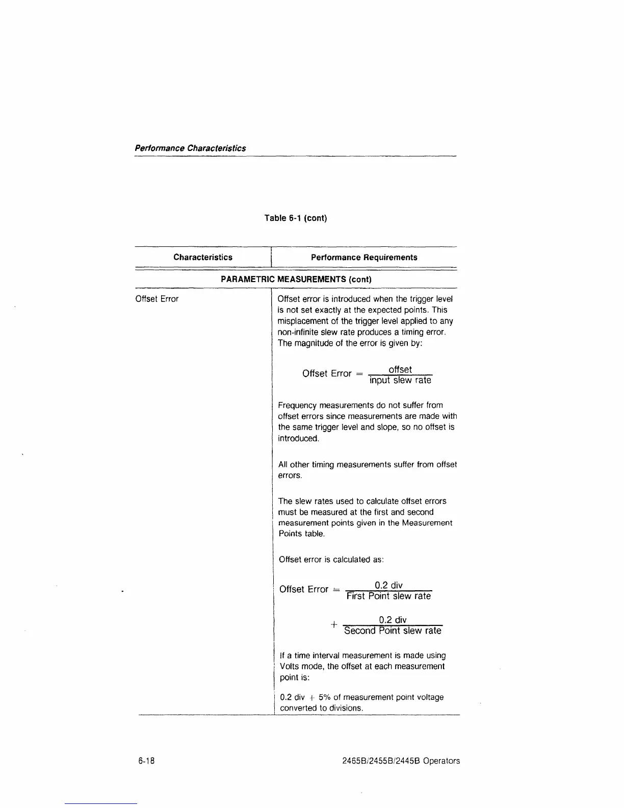
Offset Error Offset error is introduced when the trigger level
is not set exactly at the expected points. This
misplacement of the trigger level applied to any
non-infinite slew rate produces a timing error.
The magnitude of the error is given by:
Offset Error =
offset
input slew rate
Frequency measurements do not suffer from
offset errors since measurements are made with
the same trigger level and slope, so no offset is
introduced.
All other timing measurements suffer from offset
errors.
The slew rates used to calculate offset errors
must be measured at the first and second
measurement points given in the Measurement
Points table.
Offset error is calculated as:
Offset Error ±=
+
0.2 div
First Point slew rate
0.2 div
Second Point slew rate
If a time interval measurement is made using
Volts mode, the offset at each measurement
point is:
0.2 div
■[■
5% of measurement point voltage
converted to divisions.
6-18
2465B/2455B/2445B Operators
 Loading...


