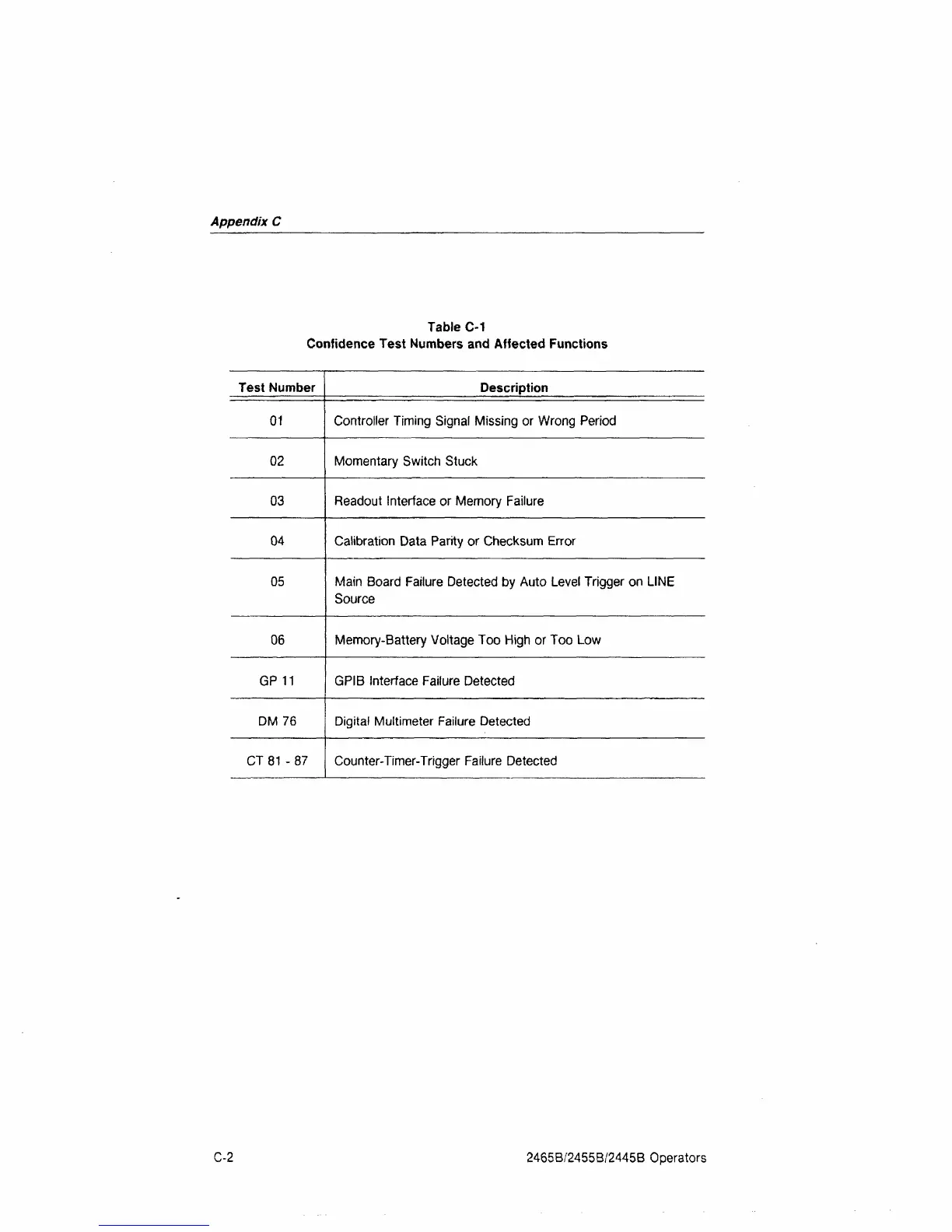
EasyManuals Logo

Tektronix 2465B Operator's Manual

Tektronix 2465B
207 pages
To Next Page IconTo Next Page
To Previous Page IconTo Previous Page
Page #188 background imageLoading...
Page #188 background image
Appendix
C
Table C-1
Confidence Test Numbers and Affected Functions
Test Number
01
02
03
04
05
06
GP 11
DM 76
CT
81
- 87
Description
Controller Timing Signal Missing or Wrong Period
Momentary Switch Stuck
Readout Interface or Memory Failure
Calibration Data Parity or Checksum Error
Main Board Failure Detected by Auto Level Trigger on LINE
Source
Memory-Battery Voltage Too High or Too Low
GPIB Interface Failure Detected
Digital Multimeter Failure Detected
Counter-Timer-Trigger Failure Detected
C-2
2465B/2455B/2445B Operators

Table of Contents

Other manuals for Tektronix 2465B

Questions and Answers:

Question and Answer IconNeed help?

Do you have a question about the Tektronix 2465B and is the answer not in the manual?

Tektronix 2465B Specifications

General IconGeneral
Bandwidth400 MHz
Channels4
Vertical Sensitivity2 mV/div to 5 V/div
Maximum Input Voltage400 V (DC + peak AC)
DisplayCRT
Trigger ModesAuto, Normal, Single
Time Base Range500 ps/div to 0.5 s/div
Rise Time875 ps
Power Supply48 to 440 Hz
Dimensions495 mm

Related product manuals