Operation
Scale
Factors
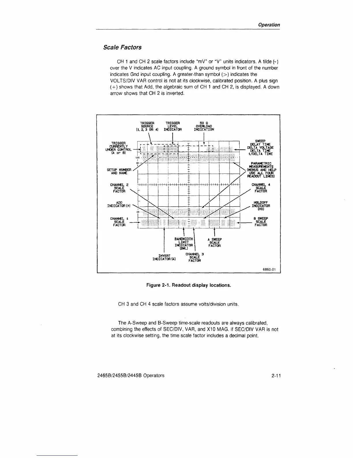
CH 1 and CH 2 scale factors include "mV" or "V" units indicators. A tilde (~)
over the V indicates AC input coupling. A ground symbol in front of the number
indicates Gnd input coupling. A greater-than symbol (>) indicates the
VOLTS/DIV VAR control is not at its clockwise, calibrated position. A plus sign
{
+
)
shows that Add, the algebraic sum of CH 1 and CH 2, is displayed. A down
arrow shows that CH 2 is inverted.
TRIGGER TRIGGER
SOURCE LEVEL
[i,
2.
3 OR
4) INDICATOR
TRIGGER
CURRENTLY
UNDER CONTROL
(A
or B)
INVERT
INDICATOR
W
SWEEP
DELAY TIKE
DELTA VOLTAGE
DELTA TIME
i/DELTA
TIME
PARAMETRIC
MEASUREMENTS
{MENUS
AND
HELP
USE
ALL
FOUR
READOUT LINES)
6860-01
Figure
2-1.
Readout display locations.
CH 3 and CH 4 scale factors assume volts/division units.
The A-Sweep and
B-Sweep
time-scale readouts are always calibrated,
combining the effects of SEC/'DIV, VAR, and X10 MAG. If SEC/DIV VAR is not
at its clockwise setting, the time scale factor includes a decimal point.
2465B/2455B/2445B Operators
2-11

 Loading...


