Phase Shift Measurements Using XY Mode
XY mode lets you display an input signal rather than the time
base on the horizontal axis. This mode lets you make phase shift
measurements. Phase shift describes the difference in timing
between two otherwise identical signals.
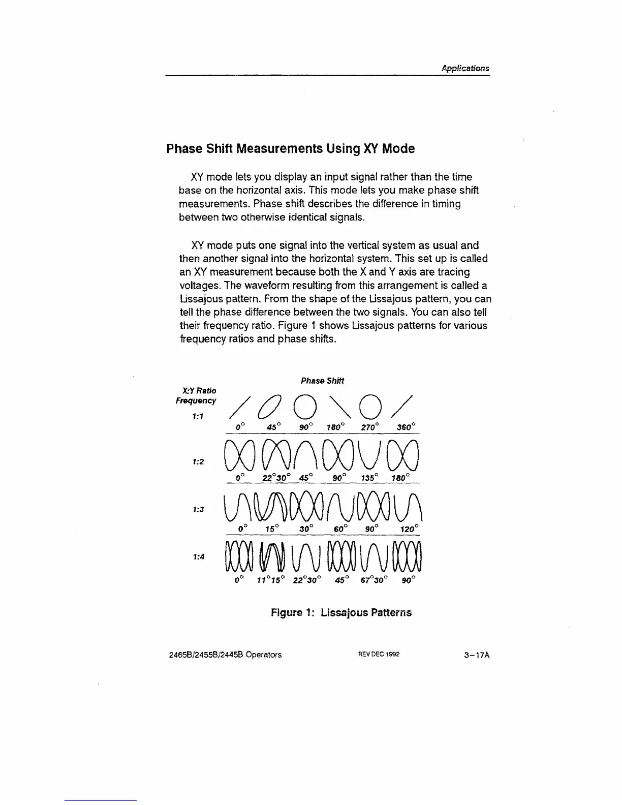
XY mode puts one signal into the vertical system as usual and
then another signal into the horizontal system. This set up is called
an XY measurement because both the
X
and Y axis are tracing
voltages. The waveform resulting from this arrangement is called
a
Lissajous pattern. From the shape of the Ussajous pattern, you can
tell the phase difference between the two signals. You can also tell
their frequency ratio. Figure
1
shows Lissajous patterns for various
frequency ratios and phase shifts.
Phase Shift
XY Ratio
Frequency
1:1
/c?o\o/
0° 45° 90° 180° 270° 360°
-
Daflnoovoo
1:3
1:4
(T iriS
v
22
v
30" 45" 67"3<T 90
Figure 1: Lissajous Patterns
2465B/2455B/2445B Operators
REV
DEC
1992
3 -17A

 Loading...


