EasyManuals Logo

Tektronix 2465B Operator's Manual

Tektronix 2465B
207 pages
To Next Page IconTo Next Page
To Previous Page IconTo Previous Page
Page #97 background imageLoading...
Page #97 background image
Controls,
Connectors,
and
Indicators
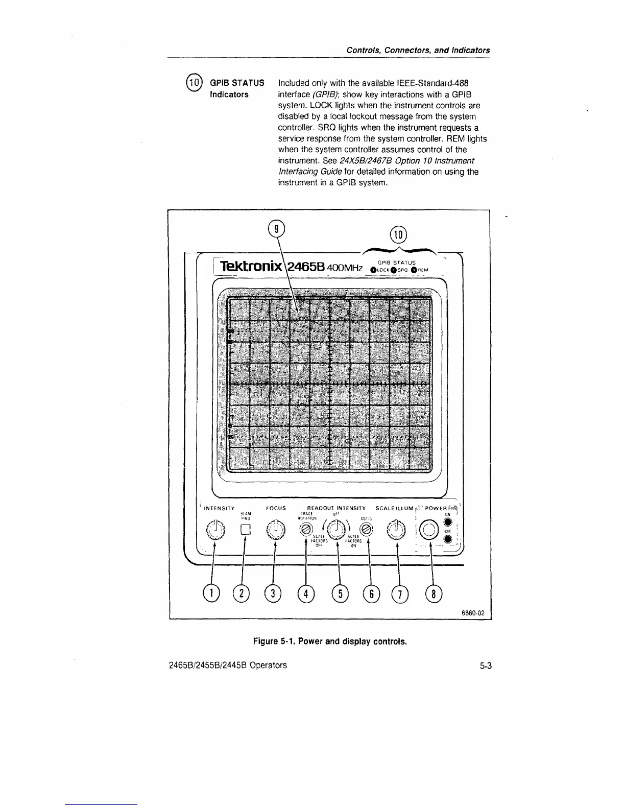
GPIB STATUS Included only with the available IEEE-Standard-488
Indicators interface
(GPIB);
show key interactions with a GPIB
system.
LOCK lights when the instrument controls are
disabled by a local lockout message from the system
controller. SRQ lights when the instrument requests
a
service response from the system controller. REM lights
when the system controller assumes control
of
the
instrument. See
24X5B/2467B Option 10 Instrument
Interfacing Guide
for detailed information on using the
instrument in a GPIB system.
"^
Z_
REAOOUT INTENSITY SCALE ILLUM *.*'' POWER
#*$&
i V^-^y V^SWH Si--i/SC4U
^—^
V i>
D
0 G
6860-02
Figure
5-1.
Power and display controls.
2465B/2455B/2445B Operators
5-3

Table of Contents

Other manuals for Tektronix 2465B

Questions and Answers:

Question and Answer IconNeed help?

Do you have a question about the Tektronix 2465B and is the answer not in the manual?

Tektronix 2465B Specifications

General IconGeneral
Bandwidth400 MHz
Channels4
Vertical Sensitivity2 mV/div to 5 V/div
Maximum Input Voltage400 V (DC + peak AC)
DisplayCRT
Trigger ModesAuto, Normal, Single
Time Base Range500 ps/div to 0.5 s/div
Rise Time875 ps
Power Supply48 to 440 Hz
Dimensions495 mm

Related product manuals