Specification—2465B/2467B Service
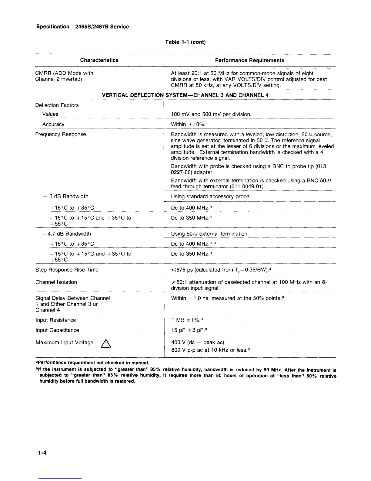
Table 1-1 (cont)
Characteristics
CMRR (ADD Mode with
Channel 2 inverted)
Performance Requirements
At least 20:1 at 50 MHz for common-mode signals of eight
divisions or less, with VAR VOLTS/DIV control adjusted for best
CMRR at 50 kHz, at any VOLTS/DIV setting.
VERTICAL DEFLECTION SYSTEM—CHANNEL 3 AND CHANNEL 4
Deflection Factors
Values
Accuracy
Frequency Response
- 3 dB Bandwidth
+ 15°C to +35°C
-15°C to +15°C and +35°C to
+ 55°C
-4.7 dB Bandwidth
+ 15°C to + 35°C
-15°C to +15°C and +35°C to
+ 55°C
Step Response Rise Time
Channel Isolation
Signal Delay Between Channel
1 and Either Channel 3 or
Channel 4
Input Resistance
Input Capacitance
Maximum Input Voltage /K
100 mV and 500 mV per division.
Within ±10%.
Bandwidth is measured with a leveled, low distortion, 50-fi source,
sine-wave generator, terminated in 50 fi. The reference signal
amplitude is set at the lesser of 6 divisions or the maximum leveled
amplitude. External termination bandwidth is checked with a 4
division reference signal.
Bandwidth with probe is checked using a BNC-to-probe-tip (013-
0227-00) adapter.
Bandwidth with external termination is checked using a BNC 50-fi
feed through terminator (011-0049-01).
Using standard accessory probe.
Dc to 400 MHz.
b
Dc to 350 MHz.
a
Using 50-fi external termination.
Dc to 400 MHz.
a b
Dc to 350 MHz.
a
=s875 ps (calculated from T
r
=0.35/BW).
a
>50:1 attenuation of deselected channel at 100 MHz with an 8-
division input signal.
Within ±1.0 ns, measured at the 50% points.
3
1 Mfi
±1%.
a
15 pF ±3pF.
a
400 V (dc + peak ac).
800 V p-p ac at 10 kHz or less.
3
a
Performance requirement not checked in manual.
b
lf the instrument is subjected to "greater than" 85% relative humidity, bandwidth is reduced by 50 MHz. After the instrument is
subjected to "greater than" 85% relative humidity, it requires more than 50 hours of operation at "less than" 60% relative
humidity before full bandwidth is restored.
1-4