Operating Information—2465B/2467B Service
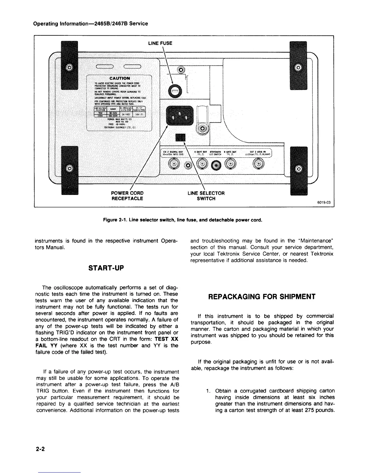
LINE FUSE
CAUTION
TO A»0iB affilftC SH£GK THE POWEB CGBtt
■
weneiwe
rawtaraate
amwctm
MUST
e?
■
wtmais
TO
waaw-
M
MW
REMOVE
COVERS-
«8FS*'S«MC«S"'lS-
- ojscswttei aim pfcwts seraffi wpweme mi.
flifi' mttmuw-ftst
fflOTfcrtoH
KKAM WIV
wrta Sfictffflj tm. m
SAKB
wist.
.smetfl«
■
:.-.
$&"■':
'■
&&*■:
:/SAȣt;
■,
38-132V
-«&■»«-.
. ■?# HST
iu.-\n
mx VA
i3*
POWER CORD
RECEPTACLE
LINE SELECTOR
SWITCH
Figure
2-1.
Line selector switch, line fuse, and detachable power
cord.
instruments is found in the respective instrument Opera-
tors Manual.
START-UP
and troubleshooting may be found in the "Maintenance"
section of this manual. Consult your service department,
your local Tektronix Service Center, or nearest Tektronix
representative if additional assistance is needed.
The oscilloscope automatically performs a set of
diag-
nostic tests each time the instrument is turned on. These
tests warn the user of any available indication that the
instrument may not be fully functional. The tests run for
several seconds after power is applied. If no faults are
encountered, the instrument operates normally. A failure of
any of the power-up tests will be indicated by either a
flashing TRIG'D indicator on the instrument front panel or
a bottom-line readout on the CRT in the form: TEST XX
FAIL YY (where XX is the test number and YY is the
failure code of the failed test).
If a failure of any power-up test occurs, the instrument
may still be usable for some applications. To operate the
instrument after a power-up test failure, press the A/B
TRIG button. Even if the instrument then functions for
your particular measurement requirement, it should be
repaired by a qualified service technician at the earliest
convenience. Additional information on the power-up tests
REPACKAGING FOR SHIPMENT
If this instrument is to be shipped by commercial
transportation, it should be packaged in the original
manner. The carton and packaging material in which your
instrument was shipped to you should be retained for this
purpose.
If the original packaging is unfit for use or is not avail-
able,
repackage the instrument as follows:
1.
Obtain a corrugated cardboard shipping carton
having inside dimensions at least six inches
greater than the instrument dimensions and hav-
ing a carton test strength of at least 275 pounds.
2-2