Theory of Operation—2465B/2467B Service
again.
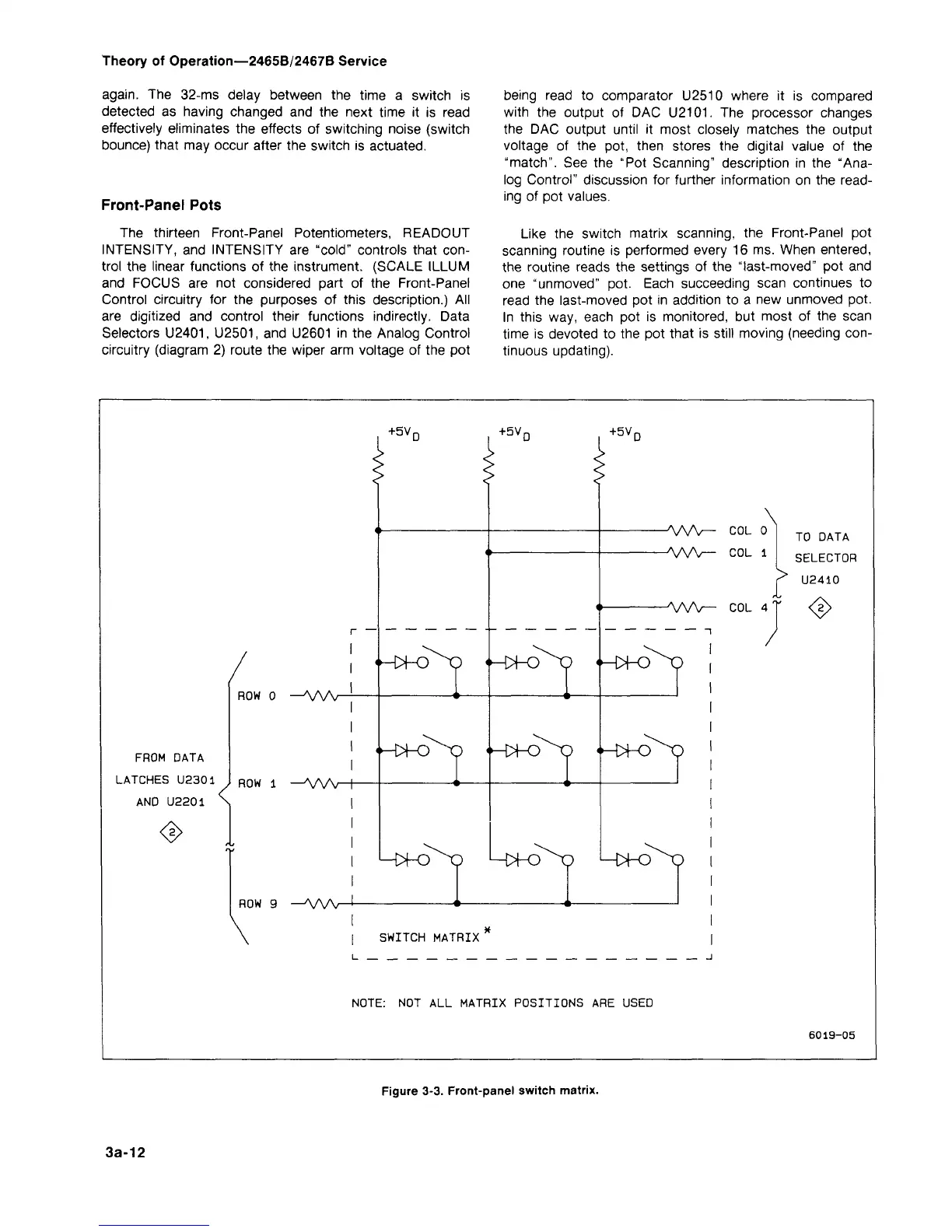
The 32-ms delay between the time a switch is
detected as having changed and the next time it is read
effectively eliminates the effects of switching noise (switch
bounce) that may occur after the switch is actuated.
Front-Panel Pots
The thirteen Front-Panel Potentiometers, READOUT
INTENSITY, and INTENSITY are
"cold"
controls that
con-
trol the linear functions of the instrument. (SCALE ILLUM
and FOCUS are not considered part of the Front-Panel
Control circuitry for the purposes of this description.) All
are digitized and control their functions indirectly. Data
Selectors
U2401, U2501,
and U2601 in the Analog Control
circuitry (diagram 2) route the wiper arm voltage of the pot
being read to comparator U2510 where it is compared
with the output of DAC
U2101.
The processor changes
the DAC output until it most closely matches the output
voltage of the pot, then stores the digital value of the
"match".
See the "Pot Scanning" description in the "Ana-
log Control" discussion for further information on the
read-
ing of pot values.
Like the switch matrix scanning, the Front-Panel pot
scanning routine is performed every 16 ms. When entered,
the routine reads the settings of the "last-moved" pot and
one "unmoved" pot. Each succeeding scan continues to
read the last-moved pot in addition to a new unmoved pot.
In this way, each pot is monitored, but most of the scan
time is devoted to the pot that is still moving (needing
con-
tinuous updating).
+5V
r
+5V
r
+5V
r
<^-o
FROM DATA
LATCHES U2301
AND U220
ROW 0 -A/W
I01 1
1 >
ROW 1
—AAAr-
^
'-^D
<^>HD
•-W-0
<^-c±o
'H^D
ROW 9 -AA/V
H>|-0
\
-A/W- COL o
-AA/V- COL i
>
-AAA^- COL 4
TO DATA
SELECTOR
U2410
♦
/
"HX-O
L-MO
SWITCH MATRIX
NOTE:
NOT ALL MATRIX POSITIONS ARE USED
6019-05
Figure 3-3. Front-panel switch matrix.
3a-12