Maintenance—2465B/2467B Service
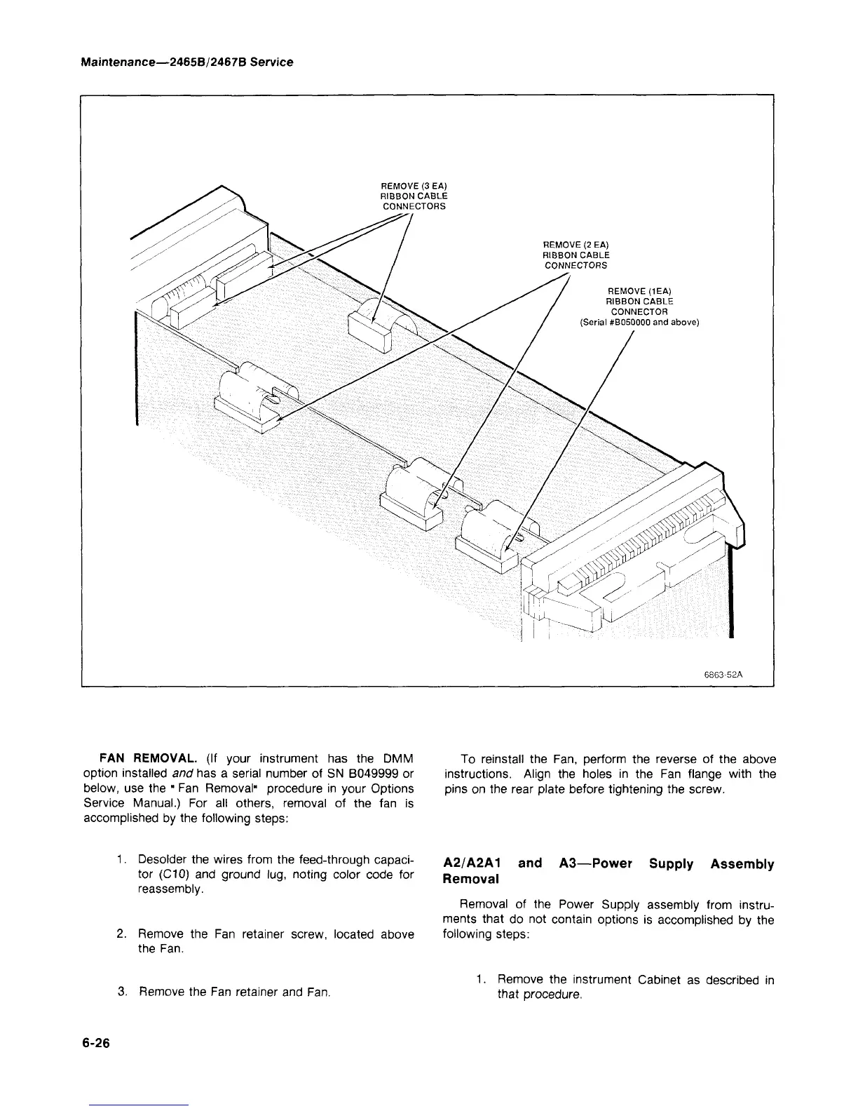
REMOVE (3 EA)
RIBBON CABLE
CONNECTORS
REMOVE (2 EA)
RIBBON CABLE
CONNECTORS
REMOVE (1EA)
RIBBON CABLE
CONNECTOR
(Serial #B050000 and above)
6863-52A
FAN REMOVAL. (If your instrument has the DMM
option installed and has a serial number of SN B049999 or
below, use the " Fan Removal" procedure in your Options
Service Manual.) For all others, removal of the fan is
accomplished by the following steps:
To reinstall the Fan, perform the reverse of the above
instructions. Align the holes in the Fan flange with the
pins on the rear plate before tightening the screw.
1.
Desolder the wires from the feed-through capaci-
tor (C10) and ground lug, noting color code for
reassembly.
Remove the Fan retainer screw, located above
the Fan.
A2/A2A1 and A3—Power Supply Assembly
Removal
Removal of the Power Supply assembly from instru-
ments that do not contain options is accomplished by the
following steps:
3. Remove the Fan retainer and Fan.
1.
Remove the instrument Cabinet as described in
that procedure.
6-26