Performance Check—2465B/2467B Service
k. Connect the CH 3 input to the WORD RECOG OUT
connector using the instrument X10 probe and a BNC-to-
probe-tip adaptor.
Recognizer to the wire on the red binding post of the
CH 2 input.
I. Set pulse generator # 1 to produce a positive
0.5-^s
pulse every 1 /us.
m. Set pulse generator # 2 to produce a positive
400-ns pulse when it receives an external trigger.
NOTE
The lowest point of the HI must not be lower
than 2.0 V.
u.
Set the A SEC/DIV to 20 ns (knob in).
2.
Check Data Setup Time
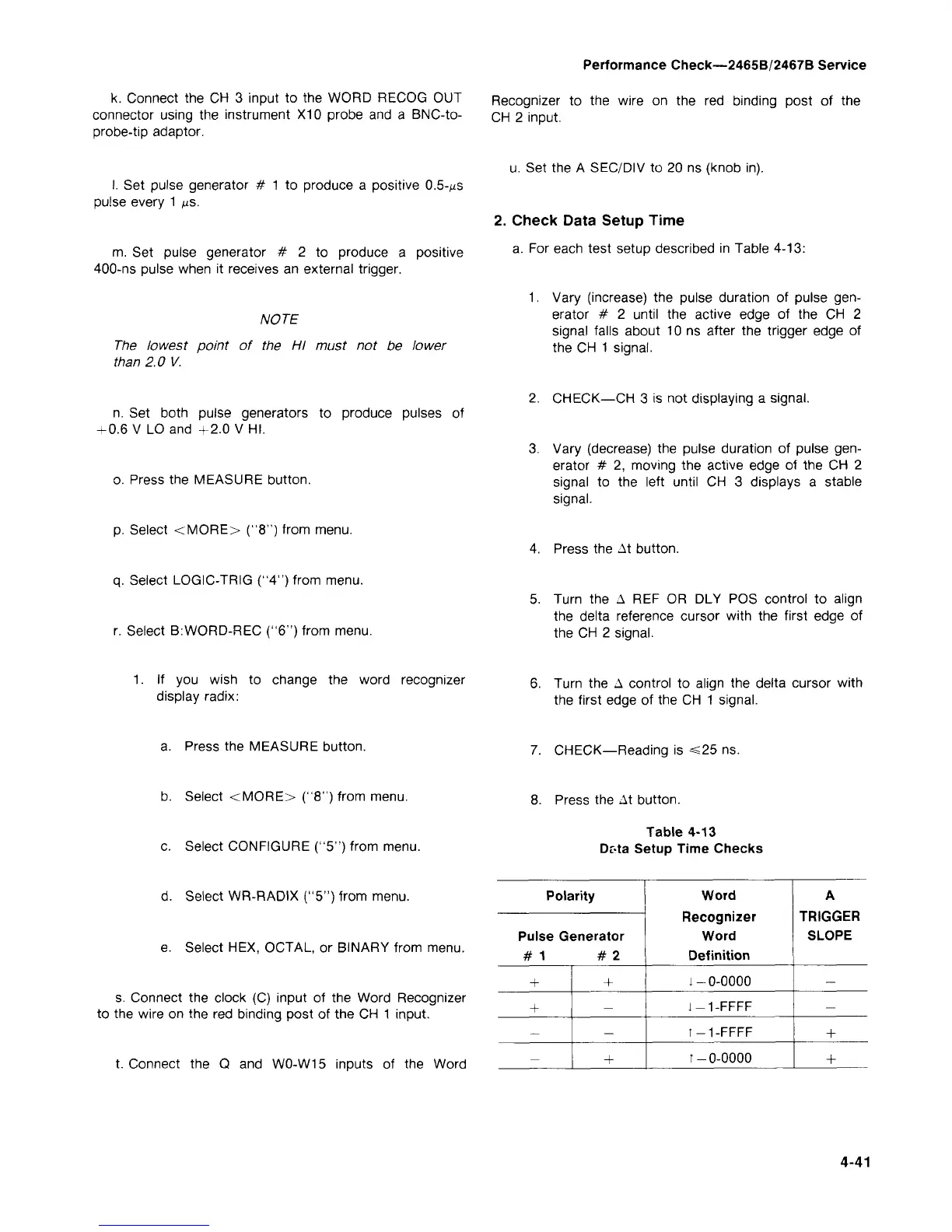
a. For each test setup described in Table 4-13:
1.
Vary (increase) the pulse duration of pulse
gen-
erator # 2 until the active edge of the CH 2
signal falls about 10 ns after the trigger edge of
the CH 1 signal.
n. Set both pulse generators to produce pulses of
-0.6 V LO and +2.0 V HI.
o. Press the MEASURE button.
p. Select <MORE> ("8") from menu.
q.
Select LOGIC-TRIG ("4") from menu.
r. Select B:WORD-REC ("6") from menu.
2.
CHECK—CH 3 is not displaying a signal.
3. Vary (decrease) the pulse duration of pulse
gen-
erator # 2, moving the active edge of the CH 2
signal to the left until CH 3 displays a stable
signal.
4.
Press the At button.
5. Turn the A REF OR DLY POS control to align
the delta reference cursor with the first edge of
the CH 2 signal.
1.
If you wish to change the word recognizer
display radix:
6. Turn the A control to align the delta cursor with
the first edge of the CH 1 signal.
a. Press the MEASURE button.
7. CHECK—Reading is <25 ns.
b. Select <MORE> ("8") from menu.
8. Press the At button.
c. Select CONFIGURE ("5") from menu.
Table 4-13
Dr-ta Setup Time Checks
d.
Select WR-RADIX ("5") from menu.
e. Select HEX, OCTAL, or BINARY from menu.
s. Connect the clock (C) input of the Word Recognizer
to the wire on the red binding post of the CH 1 input.
t. Connect the Q and W0-W15 inputs of the Word
Polarity
Pulse Generator
#1 #2
+
+
—
—
+
—
—
+
Word
Recognizer
Word
Definition
1-0-0000
i-1-FFFF
T-1-FFFF
T-0-0000
A
TRIGGER
SLOPE
—
—
+
+
4-41

 Loading...


