Adjustment Procedure—2465B/2467B Service
2.
Press and release the upper TRIGGER
COU-
PLING switch.
NOTE
If the A control is adjusted at step 9, 12 or
14, the previous step will be repeated.
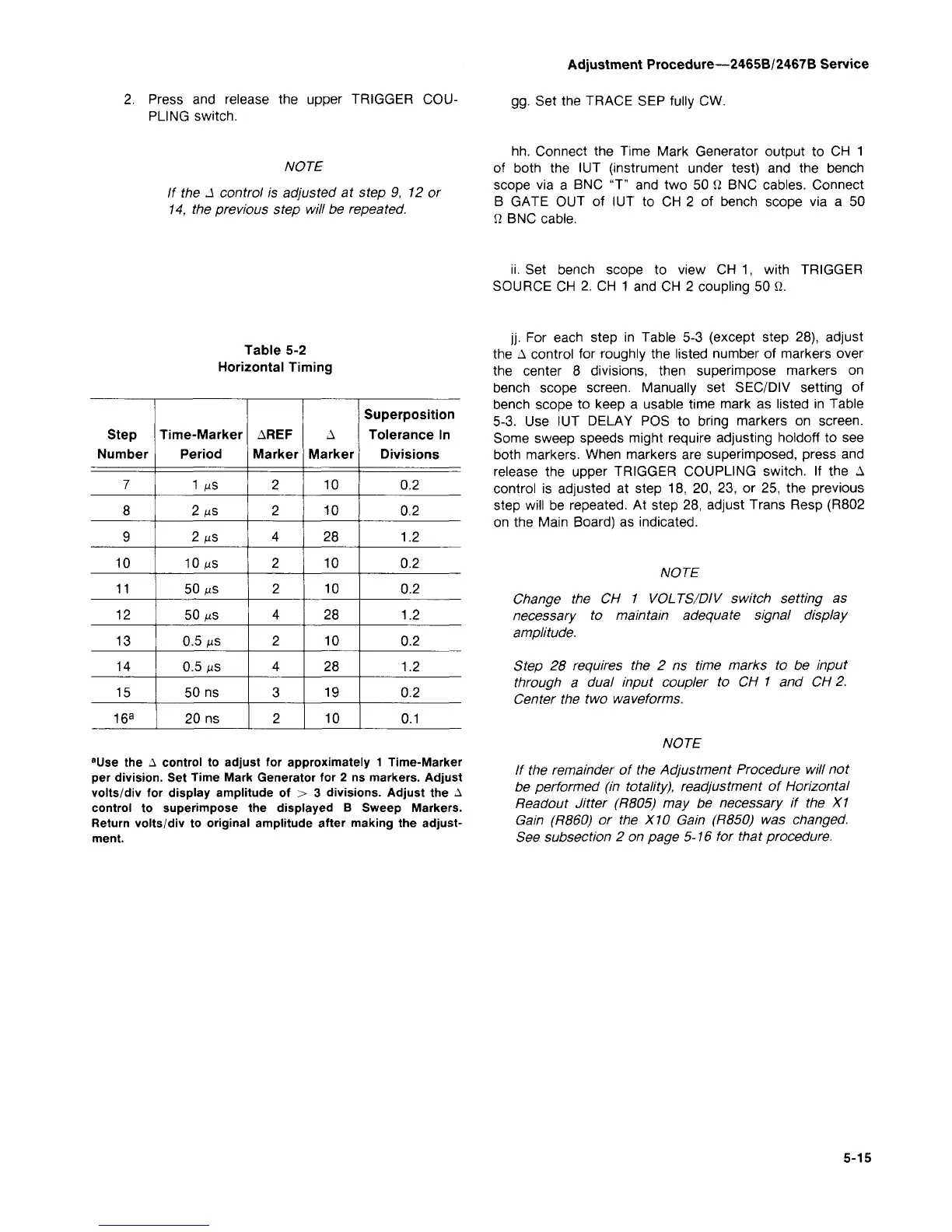
Table 5-2
Horizontal Timing
Step
Number
7
8
9
10
11
12
13
14
15
16
a
Time-Marker
Period
1 MS
2 MS
2 MS
10 MS
50 MS
50 MS
0.5 MS
0.5 MS
50 ns
20 ns
AREF
Marker
2
2
4
2
2
4
2
4
3
2
A
Marker
10
10
28
10
10
28
10
28
19
10
Superposition
Tolerance In
Divisions
0.2
0.2
1.2
0.2
0.2
1.2
0.2
1.2
0.2
0.1
a
Use the A control to adjust for approximately 1 Time-Marker
per division. Set Time Mark Generator for 2 ns markers. Adjust
volts/div for display amplitude of > 3 divisions. Adjust the A
control to superimpose the displayed B Sweep Markers.
Return volts/div to original amplitude after making the adjust-
ment.
gg.
Set the TRACE SEP fully CW.
hh.
Connect the Time Mark Generator output to CH 1
of both the IUT (instrument under test) and the bench
scope via a BNC "T" and two 50 ft BNC cables. Connect
B GATE OUT of IUT to CH 2 of bench scope via a 50
Q BNC cable.
ii.
Set bench scope to view CH 1, with TRIGGER
SOURCE CH 2. CH 1 and CH 2 coupling 50 Q.
jj.
For each step in Table 5-3 (except step 28), adjust
the A control for roughly the listed number of markers over
the center 8 divisions, then superimpose markers on
bench scope screen. Manually set SEC/DIV setting of
bench scope to keep a usable time mark as listed in Table
5-3. Use IUT DELAY POS to bring markers on screen.
Some sweep speeds might require adjusting holdoff to see
both markers. When markers are superimposed, press and
release the upper TRIGGER COUPLING switch. If the A
control is adjusted at step 18, 20, 23, or 25, the previous
step will be repeated. At step 28, adjust Trans Resp (R802
on the Main Board) as indicated.
NOTE
Change the CH 1 VOLTS/DIV switch setting as
necessary to maintain adequate signal display
amplitude.
Step 28 requires the 2 ns time marks to be input
through a dual input coupler to CH 1 and CH 2.
Center the two waveforms.
NOTE
If the remainder of the Adjustment Procedure will not
be performed (in totality), readjustment of Horizontal
Readout Jitter (R805) may be necessary if the X1
Gain (R860) or the X10 Gain (R850) was changed.
See subsection 2 on page 5-16 for that procedure.