Maintenance—2465B/2467B Service
of each component shown on that diagram. To aid in phy-
sically locating components on the circuit board, this table
also lists the grid coordinates of each component on the
circuit board illustration.
Near each circuit board illustration is an alphanumeric
listing of all components mounted on that board. The
second column in each listing identifies the schematic
diagram on which each component can be found. These
component-locator tables are especially useful when more
than one schematic diagram is associated with a particular
circuit board.
Troubleshooting Charts
The troubleshooting charts contained in the "Diagrams"
section are to be used as an aid in locating malfunctioning
circuitry. To use the charts, begin with the Preliminary
Tests flowchart. This chart will help identify problem areas
and will direct you to other appropriate charts for further
troubleshooting.
Some malfunctions, especially those involving multiple
simultaneous failures, may require more elaborate trouble
shooting approaches with references to circuit descriptions
in the "Theory of Operation" section of this manual.
Component Color Coding
Information regarding color codes and markings of
resistors and capacitors is located on the color-coding
illustration (Figure 9-1) at the beginning of the "Diagrams"
section.
RESISTOR COLOR CODE. Resistors used in this
instrument are carbon-film, composition, or precision
metal-film types. They are usually color coded with the EIA
color code; however, some metal-film type resistors may
have the value printed on the body. The color code is
interpreted starting with the stripe nearest to one end of
the resistor. Composition resistors have four stripes;
these represent two significant digits, a multiplier, and a
tolerance value. Metal-film resistors have five stripes
representing three significant digits, a multiplier, and a
tolerance value.
CAPACITOR MARKINGS. Capacitance values of
common disc capacitors and small electrolytics are marked
on the side of the capacitor body. White ceramic
capacitors are color coded in picofarads, using a modified
EIA code.
Dipped tantalum capacitors are color coded in
microfarads. The color dot indicates both the positive lead
and the voltage rating. Since these capacitors are easily
destroyed by reversed or excessive voltage, be careful to
observe the polarity and voltage rating when replacing
them.
DIODE COLOR CODE. The cathode end of each glass-
encased diode is indicated by either a stripe, a series of
stripes or a dot. For most diodes marked with a series of
stripes, the color combination of the stripes identifies three
digits of the Tektronix Part Number, using the resistor
color-code system. The cathode and anode ends of a
metal-encased diode may be identified by the diode symbol
marked on its body.
Semiconductor Lead Configurations
Figure 9-2 in the "Diagrams" section shows the lead
configurations for semiconductor devices used in the
instrument. These lead configurations and case styles are
typical of those used at completion of the instrument
design.
Vendor changes and performance improvement
changes may result in changes of case styles or lead
configurations. If the device in question does not appear to
match the configuration shown in Figure 9-2, examine the
associated circuitry or consult a manufacturer's data
sheet.
Multipin Connectors
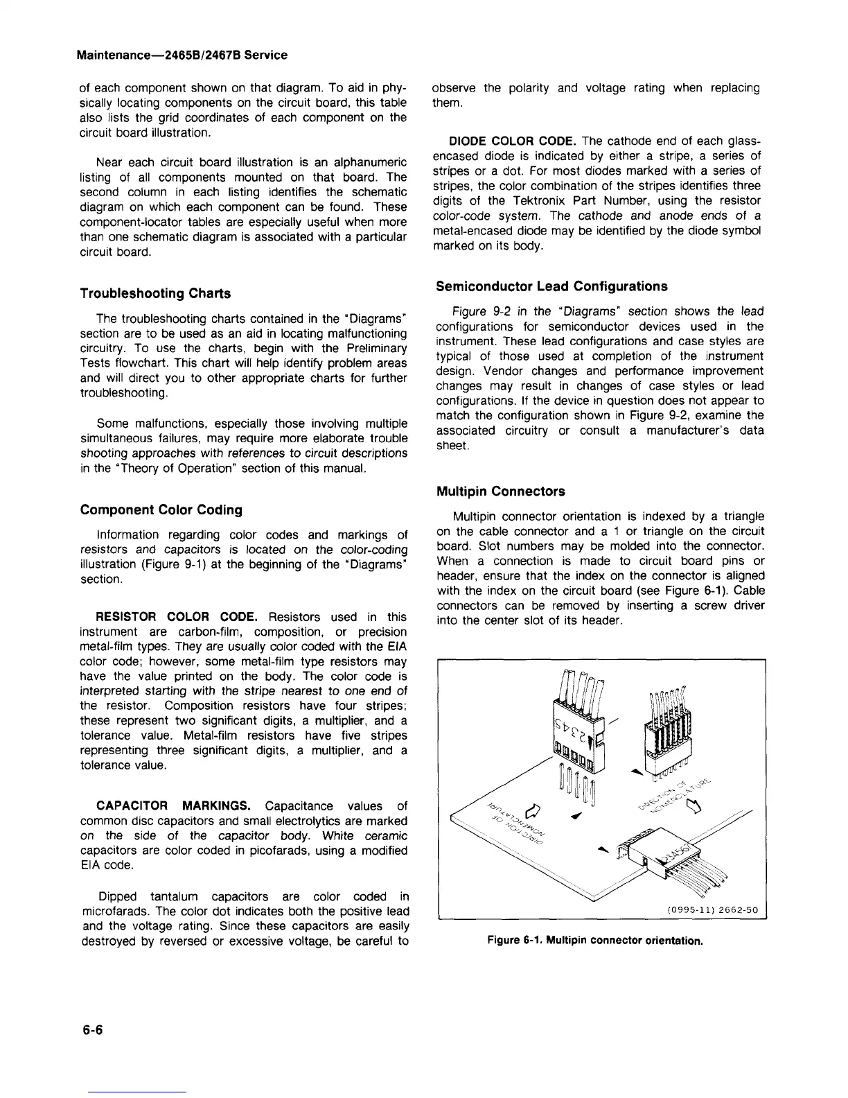
Multipin connector orientation is indexed by a triangle
on the cable connector and a 1 or triangle on the circuit
board.
Slot numbers may be molded into the connector.
When a connection is made to circuit board pins or
header, ensure that the index on the connector is aligned
with the index on the circuit board (see Figure 6-1). Cable
connectors can be removed by inserting a screw driver
into the center slot of its header.
Figure
6-1.
Multipin connector orientation.
6-6