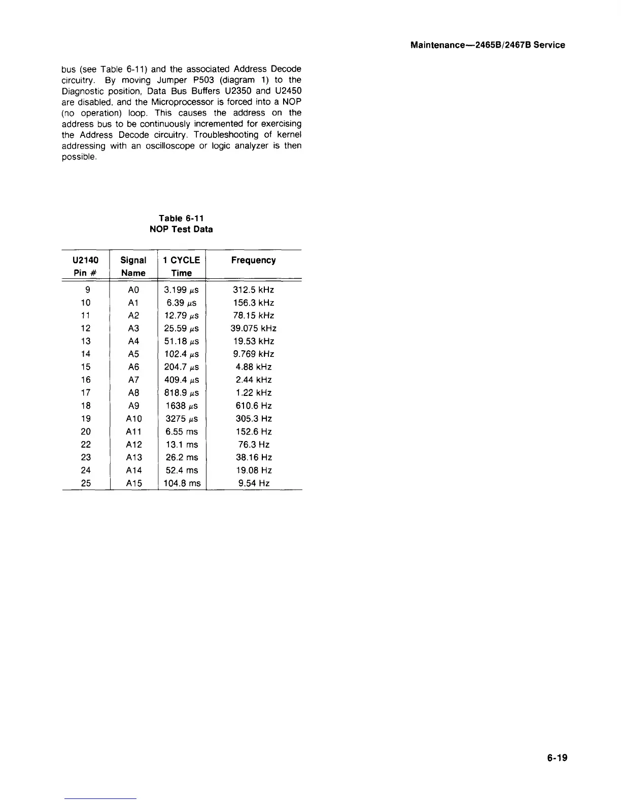
bus (see Table 6-11) and the associated Address Decode
circuitry. By moving Jumper P503 (diagram 1) to the
Diagnostic position, Data Bus Buffers U2350 and U2450
are disabled, and the Microprocessor is forced into a NOP
(no operation) loop. This causes the address on the
address bus to be continuously incremented for exercising
the Address Decode circuitry. Troubleshooting of kernel
addressing with an oscilloscope or logic analyzer is then
possible.
Table 6-11
NOP Test Data
U2140
Pin #
9
10
11
12
13
14
15
16
17
18
19
20
22
23
24
25
Signal
Name
A0
A1
A2
A3
A4
A5
A6
A7
A8
A9
A10
A11
A12
A13
A14
A15
1 CYCLE
Time
3.199 ^s
6.39 us
12.79 MS
25.59
MS
51.18 MS
102.4 MS
204.7
MS
409.4
MS
818.9 MS
1638 MS
3275
MS
6.55 ms
13.1 ms
26.2 ms
52.4 ms
104.8 ms
Frequency
312.5 kHz
156.3 kHz
78.15 kHz
39.075 kHz
19.53 kHz
9.769 kHz
4.88 kHz
2.44 kHz
1.22 kHz
610.6 Hz
305.3 Hz
152.6 Hz
76.3 Hz
38.16 Hz
19.08 Hz
9.54 Hz