Product: 2465B/2467B Service
Date:
30 JAN 93 Change Reference: M70565 REV1
DIAGRAM CHANGES (cont)
Diagram
o
EADOUT
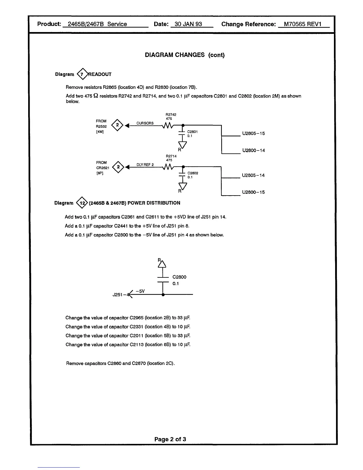
Remove resistors R2865 (location 4D) and R2830 (location 7B).
Add two 475 Q resistors R2742 and R2714, and two
0.1
[XF capacitors
C2801
and C2802 (location 2M) as shown
below.
FROM
R2S32
[4M]
♦
"
R2742
475
CURSORS
■VW-
1
C2601
0.1
U2805-15
U2800-14
FROM
CR2621
[8P]
<*>"
R2714
475
DLYREF2
-vw-
T
5
C2802
0.1
Diagram
o
U2805-14
U2800-15
(2465B & 2467B) POWER DISTRIBUTION
Add two
0.1
\lF capacitors
C2361
and C2611 to the +5VD line of
J251
pin 14.
Add a
0.1
|1F capacitor
C2441
to the +5V line of
J251
pin 8.
Add a
0.1
|1F capacitor C2800 to the -5V line of
J251
pin 4 as shown below.
1
J251
-4^
-5V
C2800
0.1
Change the value of capacitor C2965 (location 2B) to 33
(J.F.
Change the value of capacitor
C2331
(location 4B) to 10 \lF.
Change the value of capacitor
C2011
(location 5B) to 33 |XF.
Change the value of capacitor C2113 (location 8B) to 10 [IF.
Remove capacitors C2860 and C2870 (location 2C).
Page 2 of 3

 Loading...


